This guide will enable you to program machining operations larger than your machine using the “Tiling” technique. We cover both the CAD and CAM aspects in Autodesk Fusion as well as machining.
Xavier Klein
CNC Training

VCarve Pro is a trusted CAD and CAM software made specifically for CNC milling. It is easy to learn and will get you to mill your first pieces very quickly. Its bigger brother, Aspire, is an enhanced version adding 3D modeling to the functionalities.
In this tutorial, we’re going to go through the CAM section of VCarve Pro (as Aspire has basically the same) in order to mill our usual tutorial clamp. By the end of this article, you should be familiar with VCarve CAM interface and basic functions and how to use it with your Mekanika CNC Machine.
When the software is launched for the first time, it asks us to configure our machine. We are going to enter its parameters and import the Mekanika post-processor to be able to generate a G-Code that it will be able to understand.
When the Configure device window appears, click on Configure.
Note that if you miss this step, you can find the Machine configuration here: Machine menu at the top of the screen and select Machine configuration, or Add machine if you are using multiple CNCs.
In the Manage computer configuration menu, click on the cloud-shaped icon to display the Search for a computer online panel. In the Manufacturer menu, select Mekanika.

Then simply select the Series and Model corresponding to your machine.
Leave Configuration at default.

Accept the download of the configuration and click on OK to validate the configuration of the machine.

Click on Create new file, and the material dimensions panel appears, along with the main area.


1. Design workshop selector and tools, that you can switch with the tabs on the left (depending on what you want to create/import/edit). Each workshop has different tools, but the main tab will be "Design" and we will only use this one here.
2. View toolbar that allows you to switch between 2D and 3D view, hide/show layers, select parameters for the behaviour of the global display panel etc.
3. Global display, showing your drawings, toolpath, etc.
4. Toolpaths panel that can be opened by clicking on the tab on the right. It contains all the CAM interface of the software, including operation programming, toolpath display and simulation management.
Here we're going to draw a holding clamp, an essential tool for holding the stock to the sacrificial layer. We'll use this drawing to generate toolpaths and a file for the CNC.
The clamp consists of a body, a slot and a shoulder (the slot resting on the material). They are drawn with 3 rectangles and 2 circles. Although the final object will be 3-dimensional, we're going to draw it in 2d, as seen from above.
Start by clicking on the Draw Rectangle icon in the Create Vectors section.

The Design tab then displays a panel specific to this tool: Draw a rectangle.

X : 15
Y : 10
Width: 100 mm
Height: 40 mm
Click on Create and the body rectangle should appear.

Change the Anchor Point to the center point.

Position the mouse pointer in the center of the previous rectangle. Guides and magnetism should hold the point in place, then click.

The X/Y values have normally been changed to X: 65 and Y: 30.

Size:
Width: 70 mm
Height: 8 mm
Click Apply and the slot is drawn.

To finish with the rectangles, let's draw the shaft shoulder.
In the Anchor Point section, select the top right point and click on the top left corner of the first rectangle to define the X/Y positions.

Change the Sizes:
Width: 8 mm
Height: 40 mm
Click on Apply. The shoulder has been drawn, click on Close.
We're going to draw the rounded ends of the slot. Select the Draw circle tool in the Design panel.

In the Draw circle menu, make sure that the Diameter option is ticked and that its value is 8 mm.

Simply place the two circles by clicking in the middle of each short side of the slot (a symbol tells you that you're in the center of the right-hand side, and a magnetism should be felt).
Click on Close.
Now that we've drawn the clamp profile, we'll make some modifications so that the software can use it to generate toolpaths.
Click and drag to select the slot and the two circles.

In the Design panel, in the Edit Objects section, select the Weld tool.

The outer contours of the selection are then merged, deleting the lines inside:

We'll need to enlarge the shoulder a little to give some margin for the pocket operation, while retaining its original size for the contour operation. Select the shoulder rectangle and right-click > Duplicate :

Click a second time on the rectangle just duplicated to bring up the transformation tools:

Drag the white dots on the top, bottom and left sides to enlarge the rectangle:

Note that the original shoulder is still there, having been duplicated.
Now click anywhere in the document to deselect the rectangle and select the original body and shoulder rectangle by holding down the Shift key:

Click on the Weld tool to create a single object from these selections:

In the Design panel, in the Edit Objects section, select the Fillet tool.

This tool can be used to round selected corners and create dogbones if required. In the left-hand menu, set the radius to 5 mm and select Normal fillet from the list. Click on the 4 corners of the largest rectangle to create the fillets, then click on Close :

Our design is ready.
Open the Toolpaths tab on the right-hand side of the screen, and pin it so that it remains permanently open.

This panel brings together the various operations that can be performed by the software. The Set... button under the Material section lets you adjust material/stock parameters, should you need to make any adaptations.
Let's start by creating a toolpath for the shoulder.
Click on the Pocket Toolpath button.

Once in the menu, select the drawing to which you wish to apply this toolpath, in this case the rectangle representing the shoulder we've duplicated.


Units: mm
Diameter: 6 mm
No. of flutes: 3
Pass Depth: 3 mm (depth of cut, generally half the cutter diameter for wood.)
Stepover: 2.4 mm at 40%.
Spindle speed: 20000 rpm (cutter rotation speed.)
Feed units: mm/min
Feed speed: 2760 mm/min (this value can be found in Mekanika's article on speeds.)
Plunge speed: 1000 mm/min
Tool number: 1
The number of passes depends on the type of material to be machined, machine rigidity, spindle power and cutter diameter and quality. It is therefore entirely possible to optimize your passes by taking all these criteria into account. For simplicity's sake, we'll apply a general and cautious principle for wood: the maximum pass depth is equal to half the cutter diameter.
Our cutter is 6 mm in diameter, so the maximum depth of cut is 3 mm.
In this case, the cut is 4 mm deep, so we need to make 2 passes.
With the cutter configuration values set, the software automatically generates two 2mm cuts.

Note that it is entirely possible to configure the depths pass by pass in the first part of the menu or simply to decide on the number of passes directly in the last part of the menu.

The toolpaths are represented by different coloured lines:
Blue for the cutting toolpath.
Green for approaching the stock.
Red for movements outside the stock.


The 2d Profile Toolpath panel then opens.

Depths:
Tool:
Select the 6 mm cutter configured in the previous pocket operation.
Passes:
Check that the software suggests 4 passes: 12 mm / 3 mm = 4 passes. Modify if necessary by clicking on the Passes settings button. ..
Machining:
Allows you to choose the type of closed contour machining:
Outside/right: the tool will cut outside the path.
Inside/left: the tool will cut inside the path.
On: the tool will cut at the centre of the path.


Depths:
Tool:
Select the 6 mm cutter configured in the previous pocket operation.
Passes:
Check that the software suggests 4 passes: 12 mm / 3 mm = 4 passes. Modify if necessary by clicking on the Passes settings button. ..
Machining:
Tabs are used to keep the workpiece firmly attached to the stock to avoid any incidents associated with the workpiece coming off the stock, such as projections, broken bits or fire starts. It is therefore important to use them. In practice, these are unmachined parts that can be fully configured.

Length: 8 mm
Thickness: 4.0 mm
As with the depth of passes, we use conservative values: the 4 mm thickness of the tabs ensures that they do not disappear if the thickness of the stock is measured incorrectly or if the stock is not perfectly flat.


All toolpaths are now ready!
The 3 operations have been generated and can now be exported to G-code.
Before exporting, check that the order of the operations is correct:
You can rearrange the operations by dragging them with the mouse.
You can edit operations by double-clicking on them as required.
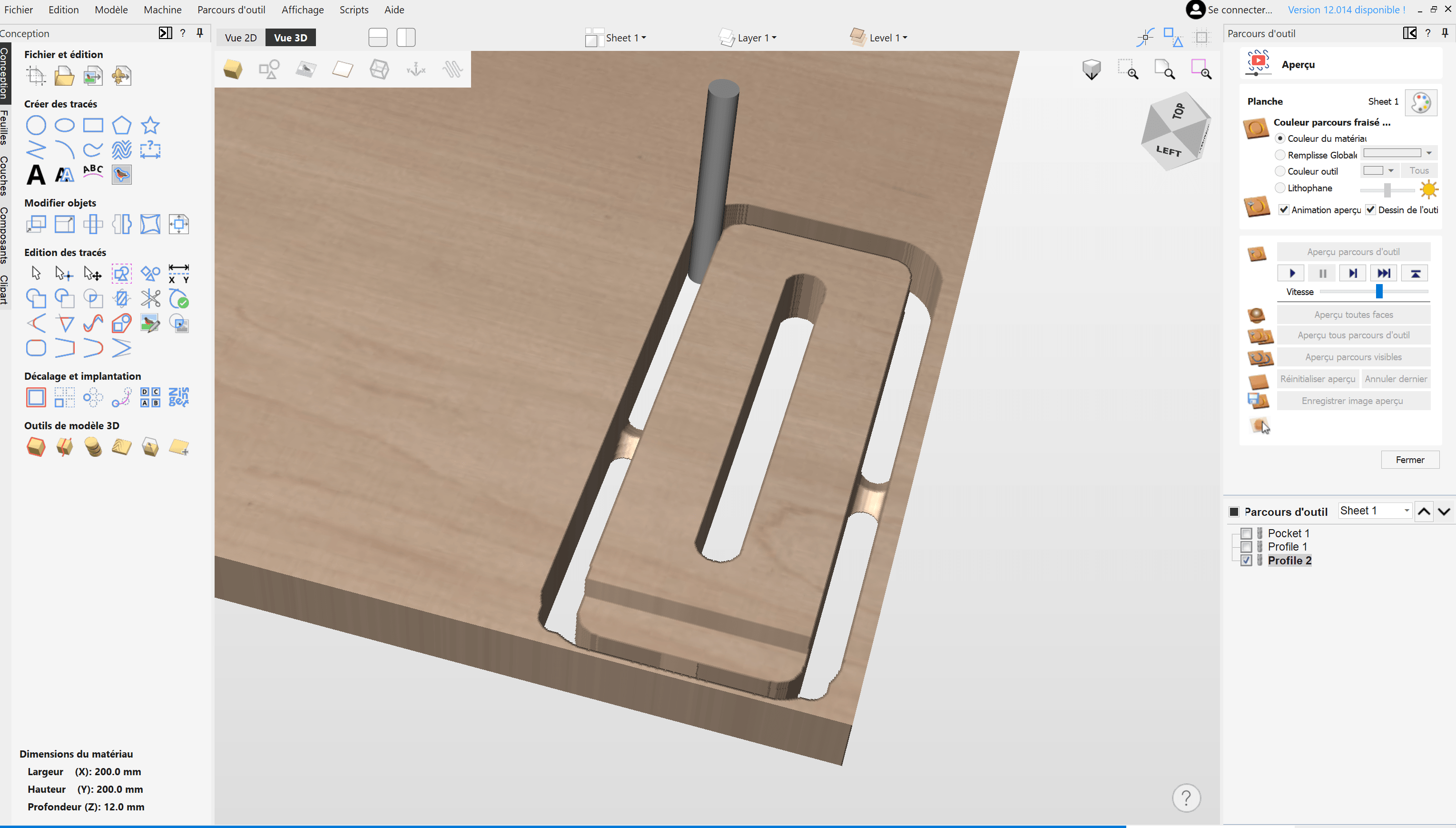
Before saving your G-code, it's a good idea to run a simulation of all the operations at reduced speed (with a preview of all the toolpaths and the cursor under the play button that lets you slow down the speed).
This allows you to spot any parasitic movements or programming errors, etc.
If everything seems coherent during the simulation, you can export your G-code to send it to the machine.
To export, click on the Save toolpaths icon:

The right-hand panel displays the export options:

We have another tutorial on how to use your Mekanika machine for the first time when you generate your G-Code, and it is adapted to any software.
Congrats, you are now able to cut your own parts using VCarve!
Mekanika is a Belgian company based in Brussels whose ambition is to make local production more accessible thanks to a 100% open-source approach.
We design and produce high quality machines for CNC milling and screen printing, which have been recognized for their reliability and ease of use. Our tools are delivered as kits and fully documented, allowing to easily adapt them to specific needs.
Visit our shop to find out more, or check out our online resources and tutorials to continue learning.

This guide will enable you to program machining operations larger than your machine using the “Tiling” technique. We cover both the CAD and CAM aspects in Autodesk Fusion as well as machining.
Xavier Klein
CNC Training

Planet CNC offers the option of starting a G-code from a specific line instead of from the beginning. This can be useful for resuming a job that was stopped for various reasons, such as a program/computer crash, a power outage or an emergency stop.
Quentin Liard
Customer Support

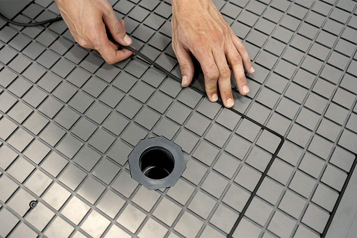
Find out how to maximize the performance of your vacuum table by learning practical tips on cutting strategies, spoilerboard maintenance and many more.
Maxime Gravet
Product Engineering