Module 3: Furniture Modeling and Joinery Design
Learn how to design a parametric stool assembled with mortise and tenon and cross lap joints, then prepare its machining in Autodesk Fusion.

Xavier Klein
CNC Educator
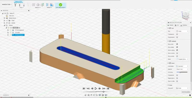
In this first module, you will model a hold-down clamp used to secure the stock to the spoilerboard, then prepare its machining all the way to the G-code. The clamp is fully parametric: you can adapt its dimensions to the thickness of your panel without redrawing the part.
What you will learn:
Prerequisites: Autodesk Fusion installed and a 2-button mouse with a scroll wheel. No prior CAD knowledge is required.
This tutorial is an in-depth version of our video tutorial available on YouTube.
This module requires the Autodesk Fusion software and a 2-button mouse with a scroll wheel.
Create a “Personal Use” account and download the free version of the software. This version is limited compared to the paid versions, but more than enough to get started. It is restricted to personal, non-commercial projects: professional use requires a paid licence.
Make sure of 2 things:
To do this:

Click on your Profile picture (top right of the screen).
Then on Preferences.
In the Preferences menu:
Check or change the settings Language > English and Default modeling orientation > Z up.
Click OK and restart the software if you changed the language.

THE INTERFACE:
1. DATA PANEL:
If it is not displayed, click the grid-shaped icon at the top left.

In Fusion, a file is called a Design. Once saved, a design becomes accessible in the Data Panel. You can create folders, called Projects, to organise your designs. With the Personal Use version, you can only have about ten editable designs at the same time. To free some up, set certain designs to read-only using the menu that appears when you right-click.
Designs can be shared with other users, and a new version is created each time you save manually (Save function). The software also regularly saves the design to the Autodesk cloud.
Save the new “Untitled” design: click File > Save (keyboard shortcut: CTRL or CMD + S).
Name it “Parametric Clamp”. In Location, click the arrow on the right to display the rest of the menu.
Click New Project and name it Mekanika Training.
You can store all the exercises from our training modules in this project.
2. TOOLBAR:
The Toolbar gathers all the tools we will need in the software.
We have already seen the Preferences.

Here are the main options of the File menu (file icon at the top left):

New Design
Creates a new design.
Recover Document
Recovers unsaved files.
Upload
Imports a file from another software (for example a .step file from SolidWorks).
Export
Saves the design locally in .f3d format (Fusion's native format) or in another format.
Just below, the drop-down menu lets you switch Workspace:

Design (stay in this workspace for now)
2D and 3D drawing workspace.
Generative Design
Generates design proposals based on constraints.
Render
Image rendering workspace for your designs.
Animation
Animated rendering workspace for your designs.
Simulation
Simulates the behaviour of the design under different conditions.
Manufacture
Machining preparation workspace.
Drawing
Technical drawing workspace.
Electronics
Electronic design workspace.
3. BROWSER:
If it is hidden, display it by clicking the two small arrows on the left edge of the screen.
The Browser lists all the elements in the design. We will come back to it later in the module.

4. VIEW CUBE:
The View Cube helps you find your way around in space. You can change the viewpoint by clicking on the different parts of the cube.

Click on the different faces and corners of the cube to see how the camera changes.
Left-click on the cube and move the mouse while holding the click to rotate freely around a pivot point located at the origin of the document.
Click the Home button (house-shaped icon) to return to the original view.
View Cube drop-down menu (click the down arrow):

Go Home
Same as the house-shaped icon.
Orthographic, Perspective, Persp. with Ortho. Faces
Lets you choose the type of view projection.
Set current view as Home
Lets you set the current view as the Home view.
Set current view as…
Lets you define the Top or Front of the design based on the current viewpoint.
5. NAVIGATION BAR:
This bar gives access to several navigation and display options.
Orbit (Shift + Middle Click): Rotates the camera around an object or a point.
Look At: Centres the camera on the selected element of the design.
Pan (Middle Click): Moves the camera sideways.
Zoom (Scroll Wheel): Zooms in or out from the mouse position.
Zoom Window: Zooms into the selected area.
Display Settings: Configures the 3D display of the software (shadows, environment colour, etc.).
Grid & Snaps: Configures the grid and its snapping.
Viewports: Splits the screen into several views, each with a different angle.
For now, we are deliberately leaving aside the Timeline located below.
We will explain it later.
See the Autodesk documentation to learn more about the Fusion interface.
We will start by defining the different parameters of our part. This step is not mandatory: you can also draw without parameters, or define them as you go along.
To do this, click Modify > Change Parameters.
When you open the menu, notice two things:

THE PARAMETERS WINDOW

A parameter is a name that you choose and to which you assign a numerical value or a character string. During design, instead of typing numerical values, you call these parameters, and therefore their associated value.
The advantage: once the design is fully parametric, you can change the values on the fly from the parameters window and the design adapts to these changes, provided the constraints have been placed correctly.
For example, our clamp will be fully parametric: you will be able to easily change its length, thickness, etc., without editing the object manually. The toolpaths will also adapt to these changes, so you can adjust your file very quickly. Note: if you enter values directly, they are still listed in the Model Parameters tab.
We will create a first parameter for the thickness of our clamp, which is also the thickness of the material we will machine. Click the + icon (Add User Parameter) to create a parameter.

Give it a name: thickness
Set its unit: mm
Set its expression (its value): 12
Click OK

Warning: to avoid confusion, a parameter name cannot contain an algebraic operator such as "-". Spaces are also not allowed: use an "_" or camelCase.
Your first parameter is created!
Now create all the other parameters we will need for the project, following this list (Name / Unit / Expression):
| thickness | mm | 12 |
| totalLength | mm | 100 |
| slotLength | mm | totalLength - 30 |
| width | mm | 40 |
| slotWidth | mm | 8 |
| shoulderDepth | mm | thickness - 4 |
| shoulderWidth | mm | 10 |

Note that you can use parameters inside other parameters, and therefore combine them with algebraic operators (+, -, /, *, etc.).
A complex file can thus contain many parameters that interact with each other. More information in the Autodesk documentation:
Using parameters in Fusion
You can also export and import all these parameters into another design by clicking the icons next to the trash can.
The object we are going to draw comes from two elements: a 2D plane called a Profile, which we will use to extrude a 3D Solid. 2D planes are drawn in a Sketch.
To create a 2D drawing, click: Create > Create Sketch

The software then asks you to choose the plane on which to place your sketch and displays the origin planes (you can also create your own planes or select a face of a 3D object).

Select the orange rectangle representing the X/Y plane (bordered by the green and red lines).
Once the plane is selected, the camera faces the X/Y plane (that is, Top on the View Cube) and the Toolbar changes to offer 2D drawing tools.
You can now create the 2D drawing of the part:
Select the Center Rectangle tool in Create > Rectangle > Center Rectangle

With the tool, click on the centre point of the sketch and move the mouse without clicking or holding the click. The rectangle is drawn and 2 input boxes appear for entering values:

In the first input box, type totalLength: the software automatically suggests the parameter as soon as you start typing. Click the suggested parameter or finish typing it by hand.
Move to the 2nd input box by pressing the TAB key on your keyboard. Enter width and confirm with Enter. Confirm the rectangle by pressing Enter again.
The dotted diagonal lines created automatically are construction lines.
For the slot in the centre of our object, draw another rectangle with the Center Rectangle tool, again starting from the origin of the document.

Use the slotLength and slotWidth parameters for this rectangle.
Draw another rectangle with the 2-Point Rectangle tool (Shortcut: R).

Place the first point on the top right corner of the large rectangle, move the mouse without clicking to the right and down, then enter the width and shoulderWidth parameters.
Use the Center Diameter Circle (Shortcut: C) tool and place the mouse at the middle of one of the vertical lines of the small inner rectangle. A triangular symbol appears: it is a constraint indicating the midpoint of the segment. Click, then move the mouse without holding the click and enter the slotWidth parameter before confirming.
Repeat the operation on the other side of the slot.
The drawing of the part is complete: click Finish Sketch at the top right of the interface.

Go back to the Home view with the View Cube. Click Create > Extrude (Shortcut: E).
Select the profile to extrude: the large rectangle, without the slot or the rectangle added on the right. Enter the thickness parameter in the input box and confirm with Enter.

You now have a block with a slot in the centre.
Fusion considers that you have finished with the sketch and hides it. It is not deleted: find it in the Browser under the name Sketch1 (Sketch3 in the screenshot below) and click the eye-shaped icon to display it again.

Repeat the extrusion with the right-hand rectangle (the one at the end of the block) using the shoulderDepth parameter.

This creates the shoulder of the clamp, which automatically joins the main block.
Look at the Browser. It now contains 2 elements:
The Browser gathers all the elements you have created. You can rename them for clarity.
ADDING FILLETS
Select the Modify > Fillet tool.
This tool creates fillets, that is, it rounds the edges.
Select the 3 vertical edges visible in your current view. The 4th is also accessible in this view: click through the solid.

Enter a value of 5 mm directly in the input box.

Confirm by clicking OK or pressing Enter.
Congratulations!
You have modeled your first fully parametric object!
Reopen the parameters window (Modify > Change Parameters) and change the values to modify the design dynamically.
Replace the value of thickness with the exact thickness, in mm, of the panel the part will be machined from (for example 18 mm).
The model automatically changes thickness. Also try changing the other parameters.

The only value we had not predefined is the fillet radius. Any value you enter is automatically added to the parameters table, in the Model Parameters section: if you change the Radius value here, the fillet radius changes. In Fusion, modeling is therefore always parametric!

THE TIMELINE
Parameters work hand in hand with the Timeline (at the very bottom of the screen).
This interface records all the operations performed, in chronological order (excluding drawing operations inside Sketches), and lets you go back to make changes to an operation without having to delete all the following operations.

Your Timeline shows the steps performed, in order:
Create sketch / Extrusion #1 / Extrusion #2 / Fillets
To change the settings of a past operation, double-click it in the Timeline, or right-click and select Edit [operation name].
The design then updates automatically with these changes.
In the workspace drop-down menu (Workspace), select Manufacture.
The Toolbar then displays the tools needed to program a toolpath.
The logic is as follows:

1. Setup: Defines the size and thickness of the stock, as well as the work axes.
2. Cutting strategies: Defines and configures the operations to perform.
3. Adding drilling operations: if the design requires them.
4. Actions: Simulation and G-code generation.
For the next steps, download our end mill library from the Mekanika Download Center and unzip the file. We will import it later.
We will start by defining a setup. This operation defines the size and thickness of your stock, as well as its work coordinates.
To do this, click Setup > New Setup

Once the panel appears on the right of the screen, make sure the Box point button is selected, then choose the point as shown in the image:

This operation defines the orientation of the part relative to the machine. The Z axis must always point upwards, and the orientation of the X and Y axes must match the position of the stock on the machine:
With the current Box Point, the part will be oriented like this:
However, if X and Y are swapped, the part ends up placed like this:
To avoid this incorrect placement, open the Orientation drop-down menu and choose one of the proposed methods to specify the position of 2 of the axes (the 3rd will be deduced automatically).
You can also click on the arrows representing the axes to reverse their direction.
For the Z axis, choose the bottom point.
Check that the coordinate system is correctly placed (that is, on the spoilerboard), exactly as in the previous screenshot.
The position of the Z axis is important: if it is placed on top of the part, you will need to take the measurement with the Z probe on your stock. If it is placed at the bottom, you will need to take it on the machine's spoilerboard.
Z origin on the stock: ideal for engraving.
Z origin on the spoilerboard: ideal for cutting.
Defining the size and thickness of the Stock:
Click the Stock tab in the Setup window.
In Mode, select Relative size box. The stock is then calculated from the size of the design, and you can add or remove material as needed.You can also define the stock manually so that it matches the actual material: select Fixed size box.

Set Stock Side Offset to 5 mm and Stock Top Offset and Stock Bottom Offset to 0 mm.
The goal: in Stock Dimensions, the Stock Height must match the thickness of your material exactly, and the width and length must be less than or equal to those of the actual material (to be sure the part fits in the stock placed on the machine).
Click OK to confirm the Setup.

Note: you can change Fusion's default values. For example, many users replace the default Stock Top Offset value (1 mm) with 0 mm. To do this, hover over the input box of the value concerned, click the three dots that appear on the right, then select Save as User Default.
Click 2D > Adaptive Clearing.

The operation settings window opens on its first tab: Tool.
Start by choosing the tool.
Click Select… (Tool)

The tool library opens. Right-click Local > Import Library.
Navigate to the folder containing Mekanika End Mills Bundle.tools (file downloaded from the Mekanika Download Center).

Click the Flat_8mm_Multi-Purpose tool (an 8 mm diameter end mill with 3 flutes).
Choose Plywood in Cutting Data, then click Select (the library closes).

Now click the Geometry tab of the 2D Adaptive Clearing operation, then select the area to machine by clicking directly on it in the design, here: the top face of the clamp shoulder.

The next tab, Heights, shows the different travel heights of the end mill. You can change them, for example to machine deeper or increase the clearance height.
Do not change anything here.

In the Passes tab:
Enable Multiple Depths (which sets the depth of cut).
Check that:
Maximum Roughing Stepdown is set to 4 mm (half the end mill diameter).
Disable Stock to Leave

In the Linking tab:
Make sure Ramp Type is set to Helix and Ramping Angle (deg) is set to 35 deg.

Click OK to finish the configuration.
The toolpath appears as shown in the image!
The coloured lines represent the movement of the centre of the end mill.

Click 2D > Slot.

Keep the same tool (it is selected automatically).
Go straight to the Geometry tab and orient the camera to select the bottom contour of the slot. Make sure you select the contour at the bottom of the part (the contour the end mill must reach).

In the Passes tab, enable Multiple Depths and enter 4 mm in Maximum Roughing Stepdown.
In the Linking tab, leave Ramp Type on Profile and enter 35 deg in Ramping Angle (deg).
Enter 300 mm in Maximum Ramp Stepdown.
Remember that you can save these values as defaults.

Click OK: the operation is programmed!
Click 2D > 2D Contour and go straight to the Geometry tab: the tool stays the same.

Select the bottom outer contour of the design.
Check that the red arrow is on the outside of the part.
If it is on the inside, click it to flip it (it indicates which side of the contour the end mill follows).
Still in the same tab, enable Tabs. This option generates tabs: small bridges of material that hold the part to the stock during machining.

Place the tabs as shown in the image above (one in the centre of each side) using the Manual Tabs button. Also set Tab Positioning to Number of tabs and enter 0 in Tabs per Contour. To delete a tab you have already placed, click it while holding the Ctrl key.
Remember to enable Multiple Depths in the Passes tab and to set Maximum Roughing Stepdown to 4 mm.

In the Linking tab, enable Ramp:
Ramping Angle (deg): 35 deg
Maximum Ramp Stepdown: 300 mm
Ramp Clearance Height: 2.5 mm

Confirm the operation.

Congratulations! All the operations are now configured!
WHY THE ORDER OF OPERATIONS MATTERS
In the Browser, the 3 operations are listed. They will be executed from top to bottom.
Outer cutting operations must always be performed last (once cut out, the part is held less firmly, or not at all). You can drag the operations to reorder them, and rename them.

To run a simulation, click the Setup to select all three operations,
then click Actions > Simulate.

Click the Play icon to start the machining animation: it helps detect any errors in the settings or in the order of operations.

In the right-hand panel, you can configure the display (with or without toolpath, with or without stock, etc.) and the playback speed, using the slider below the Play button.
Last step: generate the G-code, the file the machine will read.
Select the Setup in the Browser (to include all three operations), then click Actions > Post Process.

Start by adding the Mekanika post-processor to your local library:
Click the folder next to Post.

Search for “Mekanika” in the Post Library search bar.
Select the Mekanika post-processor, then choose Local when the software displays Select location.

Check that the Mekanika post-processor is selected in Post.
Name the file and choose the output folder (Output): a folder on your computer or directly your machine's USB stick. Then click Post to generate the code.

You can open the G-code in a text editor to see what it contains: it is a series of X/Y/Z coordinates and information on speeds, etc., that the machine reads line by line. To understand each line, consult a G-code reference online.

The Fusion work for this Module 1 is complete.
Your G-code is ready to be sent to the machine.
Mekanika es una empresa belga con sede en Bruselas cuya ambición es hacer que la producción local sea más accesible gracias a un enfoque 100% de código abierto.
Diseñamos y producimos máquinas de alta calidad para fresado CNC y serigrafía, reconocidas por su fiabilidad y facilidad de uso. Nuestras herramientas se entregan como kits y están completamente documentadas, lo que permite adaptarlas fácilmente a necesidades específicas.
Visita nuestra tienda para saber más, o consulta nuestros recursos y tutoriales en línea para seguir aprendiendo.
Learn how to design a parametric stool assembled with mortise and tenon and cross lap joints, then prepare its machining in Autodesk Fusion.
Xavier Klein
CNC Educator
Learn how to model a parametric ashtray and prepare its 3D machining in Autodesk Fusion, from roughing to finishing.
Xavier Klein
CNC Educator
Esta guía te enseña a programar mecanizados más grandes que tu máquina con la técnica de tiling. Cubre el CAD y el CAM en Autodesk Fusion, así como el propio mecanizado.
Xavier Klein
CNC Educator