In your projects, you will often need to machine the same part or perform the same operation several times, for example, to mass produce an object or repeat a specific operation. While it is entirely possible to duplicate the paths or objects to be manufactured, this can be relatively tedious, because you will then have to select them one by one in the Geometry menu, and if you decide to add or remove parts, you will have to make the changes yourself.
Therefore, Fusion offers a way to create toolpath patterns, allowing us to duplicate them at will without having to reselect the geometries. Here, we will create an IKEA-compatible pegboard to illustrate this tool.
If you only want information about the Pattern tool, you can skip ahead to the chapter entitled Last operation: Pattern.
Design: Parameters setup
So let's sketch out our parametric pegboard. As you can see, we only have one peg.

We will start by setting our parameters. The idea is to be able to create a pegboard whose size can be adjusted according to the number of pegs we want.
You can click on Modify > Change Parameters
First, we will create two parameters for the number of notches in X and Y. Be careful not to assign them any units:
- nbrSlotX = 17
- nbrSlotY = 25
Next, we will create a parameter for the thickness of our part:
The distance between each notch:
Then the length and width of the notches:
- slotLenght = 15 mm
- slotWidth = 5 mm
That leaves the width and length. These will be determined by the number of notches you want. We will therefore use a formula to ensure that our object is accurate, regardless of the number of notches.
- We will therefore multiply the number of slots by the distance between them:(nbrSlotX*distanceBTSlots)
- If we keep the formula as it is, the last notch will appear in the middle of the right-hand side:

- To avoid this, we will simply add distanceBTSlots to our formula:
width = (nbrSlotX*distanceBTSlots) + distanceBTSlots
height = (nbrSlotY * distanceBtSlots ) + distanceBtSlots
Please note! The parentheses are important for the order of calculation.
That's it, the settings are defined. Here is a summary:
| Name |
Unit |
Expression |
Value |
| nbrSlotX |
no unit |
17 |
17 |
| nbrSlotY |
no unit |
25 |
25 |
| thickness |
mm |
5 mm |
5 |
| slotLenght |
mm |
15 mm |
15 |
| slotWidth |
mm |
5 mm |
5 |
| distanceBTSlots |
mm |
20 mm |
20 |
| width |
mm |
( nbrSlotX * distanceBTSlots ) + distanceBTSlots |
360 |
| height |
mm |
( nbrSlotY * distanceBTSlots ) + distanceBTSlots |
520 |

Pegboard Drawing
Click Create > Sketch and select the X/Y plane. Once in the sketch interface, click Create > Rectangle > Center Rectangle. Place the center point in the center of the document and enter the width and height dimensions. Press Enter to confirm the drawing.

Then select Create > Slot > Overall Slot.
First enter the slotLength value, keeping the orientation at 90°:

Confirm by pressing Enter, then, moving the mouse slightly, enter the value slotWidth:

Confirm by pressing Enter:

We will place a point at the center of the construction line drawn at the same time as our slot. This point will be used to place the sketch dimensions. To do this: Create > Point:

Place the point at the center of the dotted construction line in the middle of the notch. Verify that the Midpoint constraint appears in blue.

Une fois ce point placé, nous allons à présent fixer les mesures de l'encoche par rapport aux deux bords du rectangle. Sélectionne Create > Sketch Dimension :

We need to enter two dimensions: the distance between the center point of the notch and the bottom side of the rectangle, and the distance between the center of the notch and the left side of the rectangle.
Once the Sketch Dimension tool is activated, click on the center point we just placed, then on the bottom side of the rectangle:

Set the dimension where you want and enter the distanceBTSlots parameter.

Do the same between the dotted construction line inside the notch and the left side of the rectangle:

You can see in the screenshots that there are fillets at each corner of the rectangle. Simply use the Modify > Fillet function and create fillets with a diameter of 8mm by clicking on the two right-hand corners to be filleted.

The design is complete, and you can click on Finish Sketch:

There is no need to model the rest of the notches, as we will duplicate the toolpath. You can switch to the Manufacturing workspace.
Manufacture: Setup creation
As usual, we will start by defining the Setup (Setup > New Setup). To begin, we will go directly to the Stock tab in the left pane. Enter the following values:
- Stock Side Offset: 0 mm
- Stock Top Offset: thickness
You should then obtain the values shown in the image below:

Now return to the Setup tab. Select the Stock Point at the bottom, in the lower left corner of the notch.

You can then click OK to confirm the Setup.
Manufacture: First operation, 2D Contour of the peg
We will start by creating the toolpath for the notch: 2D > 2D Contour. If you have a 5 mm diameter milling cutter, you can use the 2D > Slot operation.
We will use a 3 mm diameter cutter, the A303.030.6D from Fraiser. This is a 2-flute Downcut cutter that is suitable for cutting thin panels such as this one. Here are the speeds:

Go to the Geometry tab and select the outline of the notch. Check that the arrow is inside the outline.

In the Passes tab, check the Multiple Depth section and enter the value for the pass depth in Maximum Roughing Stepdown. Here, we have a good quality cutter on a Mekanika Pro, so we can afford to use 3 mm passes. Otherwise, use half the diameter of the cutter, in this case 1.5 mm, if you are unsure.

Finally, in the Linking tab, check the Ramp section and enter these values if you have not saved them as defaults (as a reminder, simply click on the three small dots appearing to the right of the relevant cartridge and click on Save as User Default).
Ramping Angle: 35 deg
Maximum Ramp Stepdown: 300 mm
Ramp Clearance Height: 2.5 mm

You can validate the tool path.
Manufacture: Second operation, 2D Contour of the external contour
Why create two different toolpaths? In theory, it would be entirely possible to do everything at once in a single operation. But the goal here is to duplicate the notch path, not the panel cut path, which is only done once, at the end.
Click on 2D > 2D Contour. The cutter should already be selected. Click on the outer contour once in the Geometry tab:

Please note! In the example above, the arrow is inside the outline, meaning that the milling cutter will machine inside it. We want to machine outside, so to do this, simply click on the arrow:

Don't forget the Tabs:

For the rest, proceed as in the previous operation for the Passes and Linking tabs.
Confirm by clicking OK:

Manufacture: Last Operation, Pattern
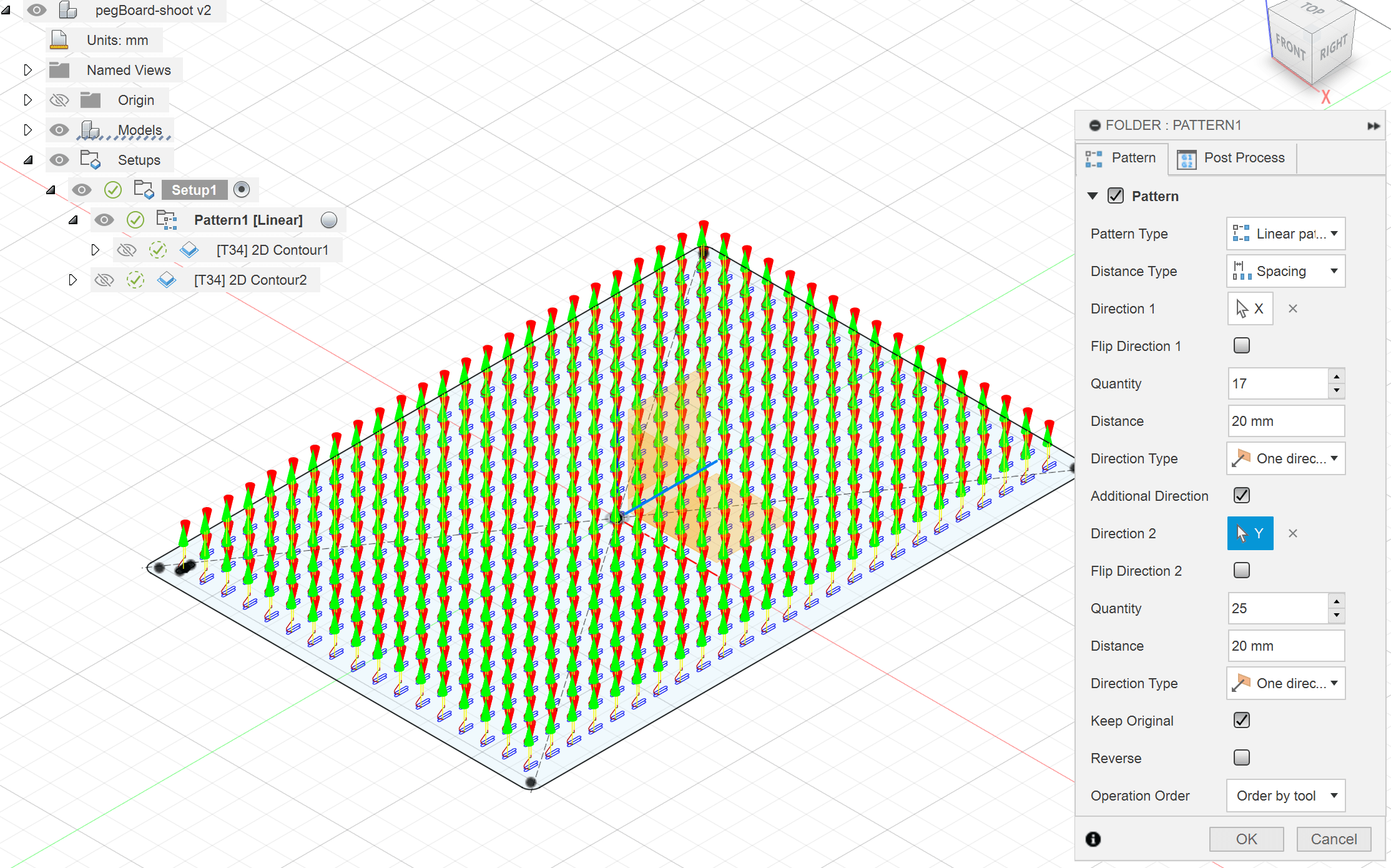
We will now create a pattern for our first operation. Right-click on the 2D Contour 1 operation, then click Add to New Pattern.

Let's take a look at the options available on the right side panel:

In the Pattern section:
Pattern Type: this is the type of pattern. It can be of different types, leave it on Linear.
Distance Type: How to calculate the distance between each element of the pattern. Spacing defines the distance between each pattern, but you can use Extend to define the total length of the pattern. Fusion then calculates the distances between each element.
Direction 1: allows you to choose the direction in which the pattern should follow by clicking on one of the axes or an edge in the design.
Flip Direction 1: allows you to swap the direction of the pattern if necessary.
Quantity: The number of elements. The number includes the original path.
Distance: Defines the distance between each element or the overall distance, depending on the type selected.
Direction Type: Allows you to choose whether the pattern goes in one direction or in two directions symmetrically.
Additional Direction: Allows you to add another direction.
Keep Original: Allows you to keep the original element or delete it.
Regarding our pattern here:
Pattern Type: Linear Pattern
Distance Type: Spacing
Direction 1: Display the axes and planes by activating the Origin folder in the Browser and select the X-axis:

Flip Direction 1: Check that the pattern is facing the correct direction. Check the option if this is not the case.

Quantity: Between the parameter nbrSlotX:

Distance: Between the parameter distanceBTSlots:

Add a second direction:
This time, select the Y axis.
Quantity: nbrSlotY
Distance: distanceBTSlots
If everything goes well, you will get this tool path grid.

Simply export by selecting Setup1 and clicking Post-Process.
If you change the settings, particularly the number of notches, don't forget to regenerate the toolpaths by right-clicking on Setup1 and selecting Generate.
There you go! If you change the number of notches, the outer contour will be modified accordingly, and you just need to regenerate the toolpaths to add them to the machining process.