Module 1: 2D Modeling and Milling
Learn the basics of Autodesk Fusion: the interface, the design of a parametric clamp and the preparation of its CNC machining.

Xavier Klein
CNC Educator
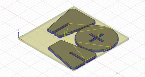
In this third module, you will design a parametric stool that assembles without screws or glue, then prepare its machining. CNC makes it quick to build this kind of furniture, thanks to joinery techniques suited to digital milling.
The stool uses the two simplest techniques:
The mortise and tenon:

The cross lap joint:

What you will learn:
Start by defining the different parameters of the stool:

| thickness | 18 mm |
| tolerance | 1 mm |
| seat | 300 mm |
| legsHeight | 400 mm |
| legsBottom | 300 mm |
| legsUp | legsBottom / 2 |
| mortiseDepth | thickness / 2 |
The tolerance parameter acts as compensation to adjust the fit of the joints.
If the joints are too tight, this parameter lets you add a few tenths of a millimetre of clearance to make assembly easier.
The mortiseDepth parameter corresponds to the depth of the mortise cut into the seat to receive the stool legs.

Create a new sketch with Create > Create Sketch and select the X/Y plane.
Draw a circle with the Create > Center Diameter Circle (Shortcut: C) tool: place it at the origin of the document and enter the seat parameter.

Draw a rectangle with the Create > Center Rectangle tool, place it at the origin and enter the legsUp parameter for the height and thickness + tolerance for the width.
Draw the same rectangle at 90° to form a cross.
Confirm the Sketch.

Select the Create > Extrude tool. Select everything except the inside of the cross and enter the thickness parameter.

Show the Sketch again in the Browser (it is hidden automatically when the extrusion is confirmed).
Select the Create > Extrude tool again, select the cross and enter the parameter mortiseDepth.

Create a new Sketch and select the top face of the seat as the reference (instead of one of the origin planes).

Redraw one of the two branches of the cross with the Center Rectangle tool and enter the thickness and legsUp parameters.

Since several bodies will be created, rename them to tell them apart easily: right-click > Rename on Body1 in the Browser and name it seat.
Then temporarily hide this body by clicking the eye icon.

Click Create > Extrude and extrude the whole Sketch2 with the -mortiseDepth parameter (with the “minus” sign so that the extrusion goes downwards).
Confirm the operation.
This will be the part of the leg that fits into the seat.
Rename this new body leg1.

Select Construct > Offset Plane.

Select the top face of leg1. Enter the parameter legsHeight.
You can confirm.

An orange rectangle appears, parallel to the selected face, 400 mm away (the value of legsHeight).
It is a new plane, on which you can draw a new sketch.

Create a new sketch on this plane and, with the Center Rectangle tool, draw a rectangle oriented the same way as the leg1 body.
Use the legsBottom and thickness parameters.

Click Finish Sketch and select the Home view.
You now see a sketch with a “floating” rectangle, 400 mm from the leg1 body.

Click Create > Loft.
Select the top face of leg1 and the “floating” sketch, Sketch3.
The Loft automatically joins the two profiles.
You can confirm.

To create the second leg, click Modify > Move/Copy (Shortcut: M).
Place the tool's pivot point at the middle of the longest face of leg1 (look for the midpoint symbol).

Before doing anything else: in the Move tool options (the panel on the right of the screen), check Create Copy.

Use the rotation handle around the Z axis and enter 90°: a second leg appears, perpendicular to the first. You can also enter 90° directly in the Z Angle input box.
Click OK to confirm the operation.

A second leg, identical to the first, has been created.

In the Browser:
Rename the new body leg2.
Hide leg2 and show Sketch1 again.

Click Create > Extrude and select the square in the centre of the sketch.

In the Extrude tool options on the right, select Start > Object.
This lets you start the extrusion from the face of another object.

Orient the view to click on the bottom face (the smallest one, where the joint fits).
Enter the legsHeight parameter.

A red volume appears: it indicates a cut through the object. Fusion enables this operation automatically when you extrude through a body.
Add legsHeight and mortiseDepth so that the cut runs along the whole length of leg1.
(do not confirm yet)

Divide this sum by 2 so that the cut only goes through half of the object.
The final expression to enter is therefore:
(legsHeight+mortiseDepth)/2
Confirm the operation and show leg2 again.

Click Modify > Combine.
In the tool options, click Target Body and select leg2 (from the Browser or by clicking directly on the 3D model).

Click Tool Bodies and select leg1. Choose the Cut operation (the middle icon).
Make sure the Keep Tools option is checked.
(it lets you use leg1 to cut leg2, without deleting leg1).

Confirm the operation and check, by changing the view, that both legs have a notch: leg1 from the bottom, leg2 from the top.
Note: with this technique, the notch in leg2 is exactly as thick as leg1, so there is no tolerance.
If you want a tolerance, model the notch in leg2 with the same method as for leg1, starting from the top instead of the bottom.


Show the seat body again.
Well done! The stool is modeled.

To add a touch of style, select the Modify > Fillet tool and round the ends of the legs with a value of 30 mm.

In the Browser, right-click the Bodies folder and click New Group to create a new group.

Select the 3 bodies (seat, leg1 and leg2) by clicking them while holding down the CTRL/CMD key.
Then right-click one of the bodies and select Copy (CTRL/CMD + C).

Then select the Group1 group, right-click it and select Paste (CTRL/CMD + V).
3 new bodies appear in Group1.
Rename Group1 to “Nesting” and hide the 3 original bodies.

Open Modify > Change Parameters and create 2 new parameters:
| stockWidth | 550 mm |
| stockDepth | 550 mm |
These parameters define the size of the material panel.
Here, we use a wooden panel cut to fit a Mekanika Evo S or Pro S, which has a working area of 630 × 630 mm.
Select Create > Create Sketch.
Draw a rectangle using the stockWidth and stockDepth parameters on the X/Y plane.

Select the Top view on the View Cube and right-click seat(1) in the group Nesting.
Click Move/Copy (Shortcut: M).

Place the seat at the bottom left of the rectangle you have just created, using the square of the Move tool.

Select Modify > Align.
Select one of the faces of leg1 or leg2.
(only the face, without selecting the anchor points that appear on hover)

Then select the top face of the seat (again without clicking an anchor point) to align the two faces.
(do not confirm yet)

Select the Front view on the View Cube to check that the two objects are properly aligned.
If they are not, click Flip in the tool menu on the right.

Repeat the operation for the second leg.
Once the 3 bodies are laid flat, move them, like the seat, into the rectangle representing the stock.
The legs are too long and too wide to fit in the panel.

Open Modify > Change Parameters.
Set legsHeight to 300 mm and legsBottom to 250 mm.
With Move/Copy (right-click the body in the Browser), position the parts so that they fit in the rectangle.

The copy of the stool is now positioned for machining, and the original assembled model is still available.

Note: the Education and paid versions of Autodesk Fusion include an Arrange function (Modify menu) that greatly simplifies this operation. It is very easy to use, but you first need to convert the bodies into components.
To learn more, read our article:
How to Use Nesting for your Complex CNC Projects
Two operations ensure that the object assembles perfectly once machined: fillets at the entrance of the cross lap joint, and dogbones in the 90° inside corners.
Dogbones compensate for the fact that an end mill, being round, cannot cut a sharp inside corner when following a contour.

The solution is to make the end mill go beyond the corner so that the joint can fit. The profile then takes on a “dog bone” shape, hence the name “dogbone”.

Start with the fillets:
Select Modify > Fillet, then the 4 edges at the entrance of the leg notches.
Enter 3 mm as the fillet value.

Confirm the operation.
DOGBONES
Fusion does not include a Dogbone function by default. To add it, follow our article:
What Are Dogbones and How to Create Them?
It is simple to use: click the face of each part and enter 8 mm as the tool diameter (Tool Diameter).

Machining preparation is similar to the previous modules, so the explanations are brief. Refer to Module 1 for more details.
Go to the Manufacture workspace. Select Setup > New Setup.
Since the stock takes all the bodies into account, it is created with the height of the assembled stool, which is not what we want.

Click Model > Select in the options and select only the 3 bodies in the Nesting group (the ones laid flat).
The stock now takes the shape of a flat panel.
Click Box point and select the X/Y point that matches the machine (bottom left).
For this exercise, place it on the spoilerboard, so below the stock (the Z probe measurement will therefore be taken on the spoilerboard).

Click the Stock tab.
Select the Fixed Size Box mode.
Unlike Relative Size Box, this mode lets you enter the stock dimensions manually:
for the Width, Depth and Thickness fields, use the stockWidth, stockDepth and thickness parameters respectively.
Set all the Model Position fields to Center.
Confirm by clicking OK.

Select 2D > 2D Pocket.

In the Tool tab, select the Flat_8mm_Multi-Purpose tool and the Plywood preset (Mekanika tool library).

In the Geometry tab, select the bottom of the cross-shaped mortise in the seat.

In the Passes tab:
Uncheck the Stock to Leave option.
Note: this option is another way to manage the tolerance.
Check the Multiple Depths option, then enter 4 mm in Maximum Roughing Stepdown.
Then move to the Linking tab.
Enable the ramp (35 deg, same settings as in Module 1) in the Linking tab, then confirm the operation.
Select 2D > 2D Contour.
The tool is carried over automatically from the previous operation.

In the Geometry tab, select the 3 contours and place tabs around each part.

In the Passes tab, check the Multiple Depths option and enter 4 mm in Maximum Roughing Stepdown.
Remember to enable the ramp in the Linking tab, as in Module 1.
Confirm the operation.
Check visually that the toolpaths have been generated correctly.

Use Actions > Simulate to simulate the machining and make sure there are no errors or collisions.

All that remains is to select Actions > Post Process to generate the G-code.
(see Module 1 for details).

Congratulations!
The stool is ready to be machined!
Mekanika es una empresa belga con sede en Bruselas cuya ambición es hacer que la producción local sea más accesible gracias a un enfoque 100% de código abierto.
Diseñamos y producimos máquinas de alta calidad para fresado CNC y serigrafía, reconocidas por su fiabilidad y facilidad de uso. Nuestras herramientas se entregan como kits y están completamente documentadas, lo que permite adaptarlas fácilmente a necesidades específicas.
Visita nuestra tienda para saber más, o consulta nuestros recursos y tutoriales en línea para seguir aprendiendo.
Learn the basics of Autodesk Fusion: the interface, the design of a parametric clamp and the preparation of its CNC machining.
Xavier Klein
CNC Educator
Learn how to model a parametric ashtray and prepare its 3D machining in Autodesk Fusion, from roughing to finishing.
Xavier Klein
CNC Educator
Esta guía te enseña a programar mecanizados más grandes que tu máquina con la técnica de tiling. Cubre el CAD y el CAM en Autodesk Fusion, así como el propio mecanizado.
Xavier Klein
CNC Educator