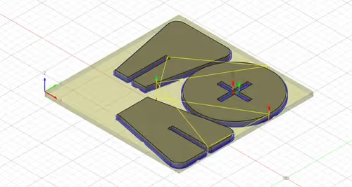
Module 3: Furniture Modeling and Joinery Design
Learn how to design a parametric stool assembled with mortise and tenon and cross lap joints, then prepare its machining in Autodesk Fusion.

Xavier Klein
CNC Educator
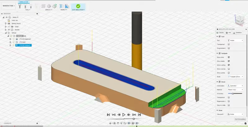
In this first module, you will model a hold-down clamp used to secure the stock to the spoilerboard, then prepare its machining all the way to the G-code. The clamp is fully parametric: you can adapt its dimensions to the thickness of your panel without redrawing the part.
What you will learn:
Prerequisites: Autodesk Fusion installed and a 2-button mouse with a scroll wheel. No prior CAD knowledge is required.
This tutorial is an in-depth version of our video tutorial available on YouTube.
Voor deze module hebt u de software Autodesk Fusion en een muis met 2 knoppen en scrollwiel nodig.
Maak een account “Persoonlijk gebruik” aan en download de gratis versie van de software. Deze versie is beperkter dan de betaalde versies, maar ruim voldoende om te beginnen. Ze is bedoeld voor persoonlijke, niet-commerciële projecten: voor professioneel gebruik hebt u een betaalde licentie nodig.
Controleer 2 zaken:
Zo doet u dat:

Klik op uw profielfoto (rechtsboven in het scherm).
Daarna op Voorkeuren.
In het menu Voorkeuren:
Controleer of wijzig de instellingen Taal > English en Modelleringsoriëntatie > Z up.
Klik op OK en start de software opnieuw als u de taal hebt gewijzigd.

DE INTERFACE:
1. DATA PANEL:
Als het niet zichtbaar is, klik dan op het rasterpictogram linksboven.

In Fusion heet een bestand een Design. Zodra een design is opgeslagen, is het toegankelijk in het Data Panel. U kunt mappen maken, Projects genoemd, om uw designs in te ordenen. Met de versie Personal Use kunt u slechts een tiental designs tegelijk bewerken. Om er vrij te maken, zet u sommige designs op alleen-lezen via het menu dat verschijnt bij een rechtermuisklik.
Designs kunnen met andere gebruikers worden gedeeld, en bij elke handmatige opslag (functie Save) wordt een nieuwe versie aangemaakt. De software slaat het design ook regelmatig op in de cloud van Autodesk.
Sla het nieuwe design “Untitled” op: klik op File > Save (sneltoets: CTRL of CMD + S).
Noem het “Parametrische spanklauw”. Klik bij Location op de pijl rechts om de rest van het menu te tonen.
Klik op New Project en noem het Mekanika Training.
In dit project kunt u alle oefeningen van onze opleidingsmodules bewaren.
2. TOOLBAR:
De Toolbar bevat alle gereedschappen die we in de software nodig hebben.
De Voorkeuren hebben we al gezien.

Dit zijn de belangrijkste opties van het menu File (bestandspictogram linksboven):

New Design
Een nieuw design aanmaken.
Recover Document
Niet-opgeslagen bestanden herstellen.
Upload
Een bestand uit andere software importeren (bijvoorbeeld een .step-bestand uit SolidWorks).
Export
Het design lokaal opslaan in .f3d-formaat (het eigen formaat van Fusion) of in een ander formaat.
Net daaronder kunt u met het vervolgkeuzemenu van Workspace wisselen:

Design (blijf voorlopig in deze werkruimte)
Werkruimte voor 2D- en 3D-tekenen.
Generative Design
Ontwerpvoorstellen genereren op basis van randvoorwaarden.
Render
Werkruimte voor beeldweergave van uw designs.
Animation
Werkruimte voor geanimeerde weergave van uw designs.
Simulation
Het gedrag van het design simuleren onder verschillende omstandigheden.
Manufacture
Werkruimte om de bewerking voor te bereiden.
Drawing
Werkruimte voor technische tekeningen.
Electronics
Werkruimte voor elektronisch ontwerp.
3. BROWSER:
Als hij verborgen is, toont u hem door op de twee kleine pijltjes aan de linkerrand van het scherm te klikken.
De Browser geeft een overzicht van alle elementen in het design. We komen er later in de module op terug.

4. VIEW CUBE:
Met de View Cube weet u waar u zich in de ruimte bevindt. U kunt van gezichtspunt wisselen door op de verschillende delen van de kubus te klikken.

Klik op de verschillende vlakken en hoeken van de kubus om te zien hoe de camera verandert.
Klik met de linkermuisknop op de kubus en beweeg de muis met ingedrukte knop om vrij te draaien rond een draaipunt op de oorsprong van het document.
Klik op de knop Home (huisjespictogram) om terug te keren naar de oorspronkelijke weergave.
Vervolgkeuzemenu van de View Cube (klik op de pijl omlaag):

Go Home
Hetzelfde als het huisjespictogram.
Orthographic, Perspective, Persp. with Ortho. Faces
Hiermee kiest u het projectietype van de weergave.
Set current view as Home
Hiermee stelt u de huidige weergave in als Home-weergave.
Set current view as…
Hiermee legt u de Top of de Front van het design vast volgens het huidige gezichtspunt.
5. NAVIGATION BAR:
Deze balk geeft toegang tot verschillende navigatie- en weergaveopties.
Orbit (Shift + klik met scrollwiel): Draait de camera rond een object of een punt.
Look At: Centreert de camera op het geselecteerde element van het design.
Pan (klik met scrollwiel): Verschuift de camera zijwaarts.
Zoom (scrollwiel): Zoomt in of uit vanaf de positie van de muis.
Zoom Window: Zoomt in op het geselecteerde gebied.
Display Settings: Stelt de 3D-weergave van de software in (schaduwen, omgevingskleur enz.).
Grid & Snaps: Stelt het raster en de magnetische uitlijning in.
Viewports: Verdeelt het scherm in meerdere weergaven, elk met een andere hoek.
De Timeline eronder laten we bewust voorlopig buiten beschouwing.
We leggen hem verderop uit.
Raadpleeg de documentatie van Autodesk voor meer informatie over de interface van Fusion.
We beginnen met het definiëren van de verschillende parameters van ons onderdeel. Deze stap is niet verplicht: u kunt ook zonder parameters tekenen, of ze gaandeweg tijdens het ontwerpen definiëren.
Klik daarvoor op Modify > Change Parameters.
Let bij het openen van het menu op twee dingen:

HET PARAMETERVENSTER

Een parameter is een naam die u kiest en waaraan u een numerieke waarde of een tekenreeks toekent. Tijdens het ontwerpen typt u geen getallen, maar roept u deze parameters op, en dus de waarde die eraan gekoppeld is.
Het voordeel: zodra het design volledig parametrisch is, kunt u meteen de waarden wijzigen in het parametervenster en past het design zich aan, op voorwaarde dat de beperkingen correct zijn geplaatst.
Onze spanklauw wordt bijvoorbeeld volledig parametrisch: u kunt de lengte, dikte enz. eenvoudig wijzigen zonder het object met de hand aan te passen. Ook de gereedschapsbanen passen zich aan, zodat u uw bestand heel snel kunt bijstellen. Let op: als u waarden rechtstreeks invoert, worden ze toch opgenomen in het tabblad Model Parameters.
We maken een eerste parameter voor de dikte van onze spanklauw, die ook de dikte is van het materiaal dat we gaan frezen. Klik op het pictogram + (Add User Parameter) om een parameter aan te maken.

Geef hem een naam: thickness
Kies de eenheid: mm
Voer de expressie (de waarde) in: 12
Klik op OK

Let op: om verwarring te vermijden, mag de naam van een parameter geen algebraïsche operator zoals "-" bevatten. Spaties zijn ook niet toegestaan: gebruik een "_" of camelCase.
Uw eerste parameter is aangemaakt!
Maak nu alle andere parameters aan die we voor het project nodig hebben, volgens deze lijst (Naam / Eenheid / Expressie):
| thickness | mm | 12 |
| totalLength | mm | 100 |
| slotLength | mm | totalLength - 30 |
| width | mm | 40 |
| slotWidth | mm | 8 |
| shoulderDepth | mm | thickness - 4 |
| shoulderWidth | mm | 10 |

Merk op dat u parameters binnen andere parameters kunt gebruiken, en ze dus kunt combineren met algebraïsche operatoren (+, -, /, * enz.).
Een complex bestand kan zo veel parameters bevatten die op elkaar inwerken. Meer informatie in de documentatie van Autodesk:
Parameters gebruiken in Fusion
U kunt al deze parameters ook exporteren en importeren in een ander design door op de pictogrammen te klikken naast de prullenbak.
Het object dat we gaan tekenen bestaat uit twee elementen: een 2D-vlak, Profiel genoemd, dat we gebruiken om een 3D-volumemodel te extruderen. 2D-vlakken tekent u in een Sketch.
Om een 2D-tekening te maken, klikt u op: Create > Create Sketch

De software vraagt u dan het vlak te kiezen waarop u uw sketch plaatst en toont de oorsprongsvlakken (u kunt ook uw eigen vlakken maken of het vlak van een 3D-object selecteren).

Selecteer de oranje rechthoek die het X/Y-vlak voorstelt (begrensd door de groene en rode lijn).
Zodra het vlak geselecteerd is, plaatst de camera zich recht tegenover het X/Y-vlak (dat wil zeggen Top op de View Cube) en verandert de Toolbar om 2D-tekengereedschappen aan te bieden.
U kunt nu de 2D-tekening van het onderdeel maken:
Selecteer het gereedschap Center Rectangle via Create > Rectangle > Center Rectangle

Klik met het gereedschap op het middelpunt van de sketch en beweeg de muis zonder te klikken of de knop ingedrukt te houden. De rechthoek wordt getekend en er verschijnen 2 invoervakken voor de waarden:

Typ in het eerste invoervak totalLength: de software stelt de parameter automatisch voor zodra u begint te typen. Klik op de voorgestelde parameter of typ hem volledig uit.
Ga naar het 2e invoervak met de TAB-toets van uw toetsenbord. Voer width in en bevestig met Enter. Bevestig de rechthoek nog eens met Enter.
De automatisch aangemaakte gestippelde diagonalen zijn constructielijnen.
Teken voor de sleuf in het midden van ons object nog een rechthoek met het gereedschap Center Rectangle, opnieuw vanaf de oorsprong van het document.

Gebruik de parameters slotLength en slotWidth voor deze rechthoek.
Teken nog een rechthoek met het gereedschap 2-Point Rectangle (sneltoets: R).

Plaats het eerste punt op de rechterbovenhoek van de grote rechthoek, beweeg de muis zonder te klikken naar rechts en naar beneden, en voer dan de parameters width en shoulderWidth in.
Gebruik het gereedschap Center Diameter Circle (sneltoets: C) en plaats de muis in het midden van een van de verticale lijnen van de kleine binnenste rechthoek. Er verschijnt een driehoekig symbool: dat is een beperking die het midden van het segment aangeeft. Klik en beweeg daarna de muis zonder de knop ingedrukt te houden, en voer de parameter slotWidth in voordat u bevestigt.
Herhaal dit aan de andere kant van de sleuf.
De tekening van het onderdeel is klaar: klik op Finish Sketch rechtsboven in de interface.

Go back to the Home view with the View Cube. Click Create > Extrude (Shortcut: E).
Select the profile to extrude: the large rectangle, without the slot or the rectangle added on the right. Enter the thickness parameter in the input box and confirm with Enter.

You now have a block with a slot in the centre.
Fusion considers that you have finished with the sketch and hides it. It is not deleted: find it in the Browser under the name Sketch1 (Sketch3 in the screenshot below) and click the eye-shaped icon to display it again.

Repeat the extrusion with the right-hand rectangle (the one at the end of the block) using the shoulderDepth parameter.

This creates the shoulder of the clamp, which automatically joins the main block.
Look at the Browser. It now contains 2 elements:
The Browser gathers all the elements you have created. You can rename them for clarity.
ADDING FILLETS
Select the Modify > Fillet tool.
This tool creates fillets, that is, it rounds the edges.
Select the 3 vertical edges visible in your current view. The 4th is also accessible in this view: click through the solid.

Enter a value of 5 mm directly in the input box.

Confirm by clicking OK or pressing Enter.
Congratulations!
You have modeled your first fully parametric object!
Reopen the parameters window (Modify > Change Parameters) and change the values to modify the design dynamically.
Replace the value of thickness with the exact thickness, in mm, of the panel the part will be machined from (for example 18 mm).
The model automatically changes thickness. Also try changing the other parameters.

The only value we had not predefined is the fillet radius. Any value you enter is automatically added to the parameters table, in the Model Parameters section: if you change the Radius value here, the fillet radius changes. In Fusion, modeling is therefore always parametric!

THE TIMELINE
Parameters work hand in hand with the Timeline (at the very bottom of the screen).
This interface records all the operations performed, in chronological order (excluding drawing operations inside Sketches), and lets you go back to make changes to an operation without having to delete all the following operations.

Your Timeline shows the steps performed, in order:
Create sketch / Extrusion #1 / Extrusion #2 / Fillets
To change the settings of a past operation, double-click it in the Timeline, or right-click and select Edit [operation name].
The design then updates automatically with these changes.
In the workspace drop-down menu (Workspace), select Manufacture.
The Toolbar then displays the tools needed to program a toolpath.
The logic is as follows:

1. Setup: Defines the size and thickness of the stock, as well as the work axes.
2. Cutting strategies: Defines and configures the operations to perform.
3. Adding drilling operations: if the design requires them.
4. Actions: Simulation and G-code generation.
For the next steps, download our end mill library from the Mekanika Download Center and unzip the file. We will import it later.
We will start by defining a setup. This operation defines the size and thickness of your stock, as well as its work coordinates.
To do this, click Setup > New Setup

Once the panel appears on the right of the screen, make sure the Box point button is selected, then choose the point as shown in the image:

This operation defines the orientation of the part relative to the machine. The Z axis must always point upwards, and the orientation of the X and Y axes must match the position of the stock on the machine:
With the current Box Point, the part will be oriented like this:
However, if X and Y are swapped, the part ends up placed like this:
To avoid this incorrect placement, open the Orientation drop-down menu and choose one of the proposed methods to specify the position of 2 of the axes (the 3rd will be deduced automatically).
You can also click on the arrows representing the axes to reverse their direction.
For the Z axis, choose the bottom point.
Check that the coordinate system is correctly placed (that is, on the spoilerboard), exactly as in the previous screenshot.
The position of the Z axis is important: if it is placed on top of the part, you will need to take the measurement with the Z probe on your stock. If it is placed at the bottom, you will need to take it on the machine's spoilerboard.
Z origin on the stock: ideal for engraving.
Z origin on the spoilerboard: ideal for cutting.
Defining the size and thickness of the Stock:
Click the Stock tab in the Setup window.
In Mode, select Relative size box. The stock is then calculated from the size of the design, and you can add or remove material as needed.You can also define the stock manually so that it matches the actual material: select Fixed size box.

Set Stock Side Offset to 5 mm and Stock Top Offset and Stock Bottom Offset to 0 mm.
The goal: in Stock Dimensions, the Stock Height must match the thickness of your material exactly, and the width and length must be less than or equal to those of the actual material (to be sure the part fits in the stock placed on the machine).
Click OK to confirm the Setup.

Note: you can change Fusion's default values. For example, many users replace the default Stock Top Offset value (1 mm) with 0 mm. To do this, hover over the input box of the value concerned, click the three dots that appear on the right, then select Save as User Default.
Click 2D > Adaptive Clearing.

The operation settings window opens on its first tab: Tool.
Start by choosing the tool.
Click Select… (Tool)

The tool library opens. Right-click Local > Import Library.
Navigate to the folder containing Mekanika End Mills Bundle.tools (file downloaded from the Mekanika Download Center).

Click the Flat_8mm_Multi-Purpose tool (an 8 mm diameter end mill with 3 flutes).
Choose Plywood in Cutting Data, then click Select (the library closes).

Now click the Geometry tab of the 2D Adaptive Clearing operation, then select the area to machine by clicking directly on it in the design, here: the top face of the clamp shoulder.

The next tab, Heights, shows the different travel heights of the end mill. You can change them, for example to machine deeper or increase the clearance height.
Do not change anything here.

In the Passes tab:
Enable Multiple Depths (which sets the depth of cut).
Check that:
Maximum Roughing Stepdown is set to 4 mm (half the end mill diameter).
Disable Stock to Leave

In the Linking tab:
Make sure Ramp Type is set to Helix and Ramping Angle (deg) is set to 35 deg.

Click OK to finish the configuration.
The toolpath appears as shown in the image!
The coloured lines represent the movement of the centre of the end mill.

Click 2D > Slot.

Keep the same tool (it is selected automatically).
Go straight to the Geometry tab and orient the camera to select the bottom contour of the slot. Make sure you select the contour at the bottom of the part (the contour the end mill must reach).

In the Passes tab, enable Multiple Depths and enter 4 mm in Maximum Roughing Stepdown.
In the Linking tab, leave Ramp Type on Profile and enter 35 deg in Ramping Angle (deg).
Enter 300 mm in Maximum Ramp Stepdown.
Remember that you can save these values as defaults.

Click OK: the operation is programmed!
Click 2D > 2D Contour and go straight to the Geometry tab: the tool stays the same.

Select the bottom outer contour of the design.
Check that the red arrow is on the outside of the part.
If it is on the inside, click it to flip it (it indicates which side of the contour the end mill follows).
Still in the same tab, enable Tabs. This option generates tabs: small bridges of material that hold the part to the stock during machining.

Place the tabs as shown in the image above (one in the centre of each side) using the Manual Tabs button. Also set Tab Positioning to Number of tabs and enter 0 in Tabs per Contour. To delete a tab you have already placed, click it while holding the Ctrl key.
Remember to enable Multiple Depths in the Passes tab and to set Maximum Roughing Stepdown to 4 mm.

In the Linking tab, enable Ramp:
Ramping Angle (deg): 35 deg
Maximum Ramp Stepdown: 300 mm
Ramp Clearance Height: 2.5 mm

Confirm the operation.

Congratulations! All the operations are now configured!
WHY THE ORDER OF OPERATIONS MATTERS
In the Browser, the 3 operations are listed. They will be executed from top to bottom.
Outer cutting operations must always be performed last (once cut out, the part is held less firmly, or not at all). You can drag the operations to reorder them, and rename them.

test
Last step: generate the G-code, the file the machine will read.
Select the Setup in the Browser (to include all three operations), then click Actions > Post Process.

Start by adding the Mekanika post-processor to your local library:
Click the folder next to Post.

Search for “Mekanika” in the Post Library search bar.
Select the Mekanika post-processor, then choose Local when the software displays Select location.

Check that the Mekanika post-processor is selected in Post.
Name the file and choose the output folder (Output): a folder on your computer or directly your machine's USB stick. Then click Post to generate the code.

You can open the G-code in a text editor to see what it contains: it is a series of X/Y/Z coordinates and information on speeds, etc., that the machine reads line by line. To understand each line, consult a G-code reference online.

The Fusion work for this Module 1 is complete.
Your G-code is ready to be sent to the machine.
Mekanika is een Belgisch bedrijf gevestigd in Brussel dat als ambitie heeft om lokale productie toegankelijker te maken dankzij een 100% open-source benadering.
We ontwerpen en produceren CNC frees- en zeefdrukmachines van hoge kwaliteit die een reputatie hebben opgebouwd voor betrouwbaarheid en gebruiksgemak. Onze gereedschappen worden geleverd in volledig gedocumenteerde kits, zodat ze gemakkelijk kunnen worden aangepast aan specifieke behoeften.
Bezoek onze Store om meer te weten te komen, of bekijk onze online bronnen en tutorials om verder te leren.
Learn how to design a parametric stool assembled with mortise and tenon and cross lap joints, then prepare its machining in Autodesk Fusion.
Xavier Klein
CNC Educator
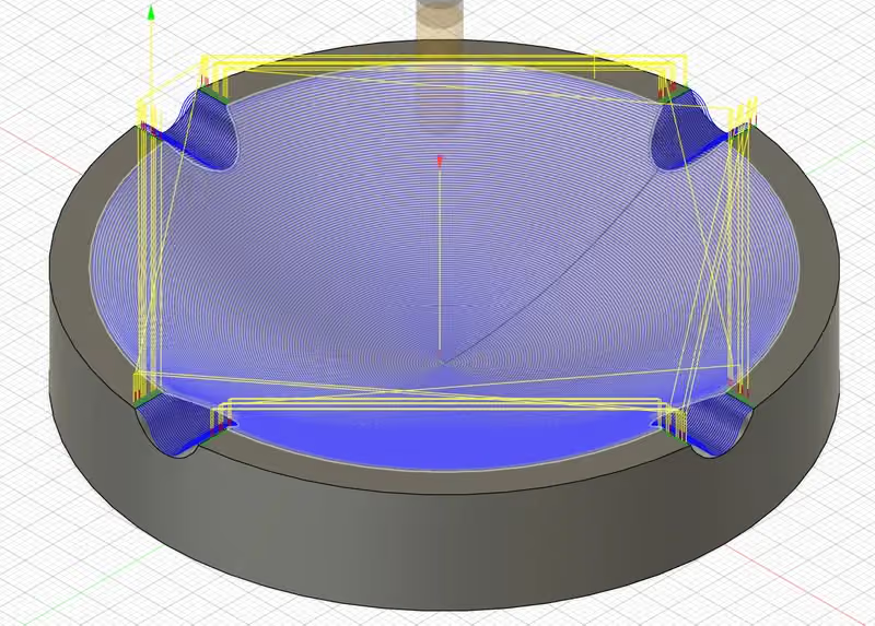
Learn how to model a parametric ashtray and prepare its 3D machining in Autodesk Fusion, from roughing to finishing.
Xavier Klein
CNC Educator
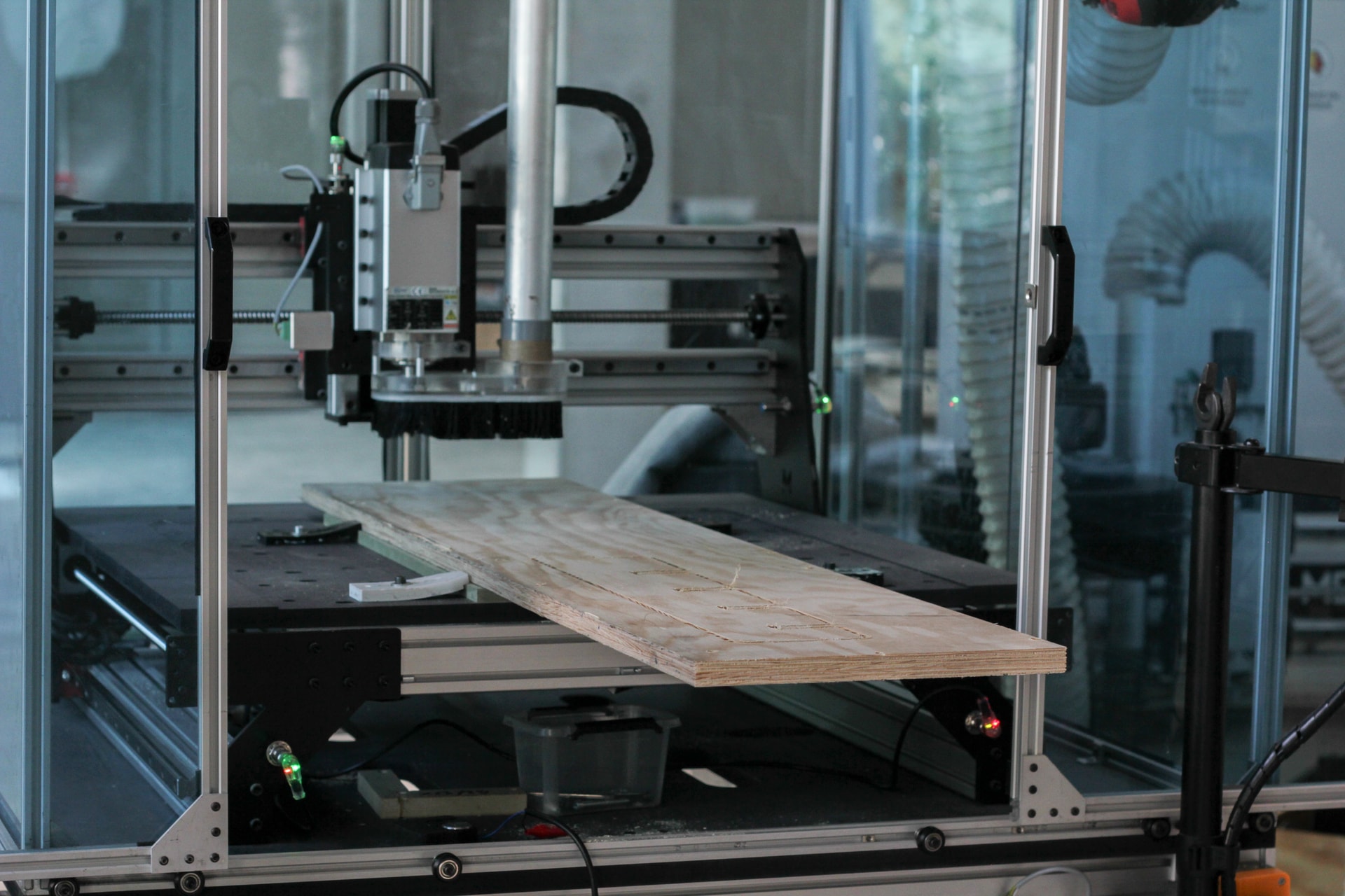
Deze handleiding leert u bewerkingen te programmeren die groter zijn dan uw machine, met de tiling-techniek. Ze behandelt CAD en CAM in Autodesk Fusion, en de bewerking zelf.
Xavier Klein
CNC Educator