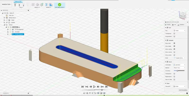
Module 1: 2D Modeling and Milling
Learn the basics of Autodesk Fusion: the interface, the design of a parametric clamp and the preparation of its CNC machining.

Xavier Klein
CNC Educator
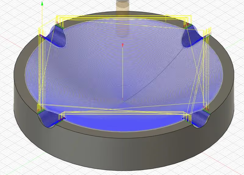
In this second module, you will model a parametric ashtray, then prepare its 3D machining. This project introduces new modeling tools and the two key steps of 3D milling: roughing and finishing.
What you will learn:
Prerequisites: having completed Module 1: 2D Modeling and Milling.
Mekanika CNC milling machines work on 3 axes (X, Y, Z). 3D machining is therefore limited to bas-relief: the end mill can only reach surfaces visible from above, unlike a 4- or 5-axis machine. For example:


Note: it is possible to machine a part on several faces by flipping it over. This module does not cover this type of operation.
We are going to model a parametric ashtray in order to machine it.
Create a new Design, name it “ashtray” and save it in the Mekanika Training project.
Machining an ashtray out of wood may seem odd, but its design and manufacture cover many concepts: revolve extrusion, custom planes, offsets and patterns, in addition to 3D machining operations.
Create the Parameters for this design:
| radius | 50 mm |
| thickness | 18 mm |
| nbrSlot | 4 unitless |
| diamSlot | 12 mm |
| offset | 3 mm |
| depthSlot | 2 mm |
Create a new Sketch and place it on the Y/Z plane (blue and green).

Once in sketch editing mode, select Create > Rectangle > 2-Point Rectangle (Shortcut: R).

Draw a rectangle starting from the origin of the document: enter the radius parameter for the width and thickness for the height.
Select the Create > Conic Curve tool.
This tool makes it easy to draw curves: we use it to model the curvature of the bowl.

Place the first point on the origin of the document, then the second point on the top right corner of the rectangle.

The next step is to define the point from which the curvature is calculated.
Choose the midpoint of the bottom edge of the rectangle: the triangular symbol appears.

Set the Rho value to 0.5, then confirm with Enter.
Rho is a coefficient that determines the shape of the curve. Its value must be between 0 and 0.99.
Press Enter once more to confirm the drawing.

Select Modify > Offset (Shortcut: O):

Select the curve: an input box appears for entering the offset distance.
Enter the offset parameter, offsetting the curve upwards as shown in the image, then click OK.

Click Finish Sketch to confirm the drawing, then the Home button to return to the default view.

Select the Create > Revolve tool.
Select the area between the two curves as well as the bottom profile:

Click Axis Select to select the line used as the axis of rotation.
Here, the Z axis or the left side of the rectangle. The revolve extrusion is then created automatically.
Click OK to confirm it.


We will now draw the 4 slots, in a sketch tangent to the edge of the ashtray. To do this, Fusion lets you create new planes on which to place a sketch.
Click Construct > Tangent Plane.

Select the cylindrical face to display an orange plane, then click OK.
Note: the Construct menu offers several ways to create planes. In Module 3, we will see how to create a plane by offsetting it from another plane.

A Construction folder appears in the Browser. It contains a Plane1 object, which you can hide or show.

Create a new sketch with Create > Create Sketch and select the plane you have just created.
The goal is to draw a line starting from the midpoint of the top edge of the cylinder, in order to draw the circle that will form the slot profile. However, the sketch cannot snap directly to this edge, because the Body and the Sketch are not linked.
You can nevertheless project edges of the Body into the sketch with the Create > Project/Include > Project (Shortcut: P) command.

Click the top edge of the cylinder, then OK to create a projected line. This line (in purple) is linked to the Body by default: it will therefore follow any changes made to it.
Select the Create > Line (Shortcut: L) tool and place the first point at the middle of the projected line (look for the triangular symbol).
Place the second point by moving the mouse (without clicking) 90° upwards, and enter the depthSlot parameter in the distance input box. Confirm with Enter.

Select this line and, in the Sketch Palette on the right of the screen, click Linetype: Construction:

The line becomes a construction line, which is ignored when selecting profiles (for an extrusion, for example). It now appears dotted.

With Create > Circle > Center Diameter Circle, draw a circle centred on the end of the construction line, using the diamSlot parameter as the diameter.
Click Finish Sketch and return to the original view with the Home button.

Run Create > Extrude, select both parts of the circle and enter the -radius parameter.
Since the extruded object passes through the ashtray, Fusion deduces that it is a cut and displays it in transparent red. This is the intended result here, but the Operation menu also lets you create a new Body or join the extrusion to the existing body.

Click OK: the first slot is created.

Select the Create > Pattern > Circular Pattern tool.
This tool duplicates a body, a component or even a face.
It can also duplicate operations in a circular way, like our last extrusion.

In the tool menu, select Object type > Features.

Below, click Objects Select, then the extrusion operation in the Timeline.

Then select Axis Select and click the Z axis.

In the input box, enter the nbrSlot parameter and click OK to confirm the operation.

The 4 slots are in place: the parametric ashtray is complete!
Go to the Manufacture workspace and create a new Setup.
Place the Box point on the bottom corner of the stock, as in Module 1.
In the Stock tab, keep Relative size box and enter 0 mm for Stock Top Offset and Stock Bottom Offset, and 1 mm for Stock Side Offset.
Check that the values in Stock Dimensions are consistent, then click OK.

Click 3D > Adaptive Clearing.
Choose the tool in Tool: Select...
Choose the Flat_6mm_Multi-Purpose end mill with the Plywood preset.

Pay close attention to the thickness of your material: an end mill has a limited cutting length. If you forget this, the collet can collide with the stock.


Move to the next tab, Geometry:
In Machining Boundary, select Selection.

Select the 5 faces to rough out: the 4 slots and the bowl. The machining boundaries appear as green lines.

Move to the Passes tab:
Uncheck Stock to Leave, enter 3 mm for Maximum Roughing Stepdown, then 0.5 mm for Fine Stepdown.
Click OK to confirm the operation.

The end mill goes down 3 mm with each pass, then refines the shape in 0.5 mm steps. This type of operation can be demanding for less powerful computers: you can reduce the load by increasing the Fine Stepdown value, which generates fewer toolpaths. As the simulation below shows, this roughing leaves visible steps on curved surfaces.

To smooth out these steps, a second operation uses a ball end mill, which follows the curvature without leaving steps.
Create a second operation 3D > Spiral.
The choice of finishing operation depends largely on your design. Feel free to test several if the choice is not obvious. In this example, other operations give equivalent machining times: Scallop, Parallel, Radial, etc.

Choose the tool in Tool: Select...
The current list does not contain a ball end mill, so you need to create one.
Click Local > Library, then the + symbol to add a new tool.

Select the end mill type, here Ball end mill.

General tab:
Description: name the tool 6mm Ball End Mill.
The other fields are optional.

Cutter tab:
Type: Ball end mill
Unit: Millimeters
Clockwise spindle...: Checked
Number of flutes: 2
Material: Carbide
Geometry section:
Diameter: 6 mm
Shaft diameter: 6 mm
Overall length: 36 mm
Length below holder: 24 mm
Shoulder length: 21 mm
Flute length: 18 mm

The number of flutes determines the cutting speeds.
The lengths are important to avoid collisions.
Collision risks are flagged during the simulation.
Skip the Shaft and Holder tabs and move to Cutting Data.
Cutting Data tab:
Click the + symbol to create a new Preset.
Name it Plywood.

Fields marked "Fx" are linked: changing one changes the others.
The most important value is Feed per tooth, determined by the ideal chip load (the ideal chip thickness).
To learn more, read our dedicated article on feeds and speeds:
Feeds and speeds guide
You can also calculate the ideal speeds with our calculator:
Mekanika speed calculator
To find the right speed ratio, use the beginner table in the article above.

Enter 0.08 mm in the Feed per tooth field and press Enter to confirm.
Notice how the other values adjust automatically.
Enter 18,000 rpm in the Spindle Speed field and press Enter to confirm.
Notice how the other values adjust automatically.
Enter 1400 mm/min in Ramp feedrate and 35 degrees for Ramp Angle.
Select Disabled in the Coolant field (at the very bottom).

Post-Processor tab:
Do not change anything.
The “Number” field corresponds to the tool's position in the magazine of a machine with an automatic tool changer.
Click Accept to confirm the creation of the tool.
Then select the newly created tool in the tool library.

Move to the Geometry tab of the Spiral operation.
Set these parameters:
Machining Boundary: Selection
Machining Boundary Selection: Same faces as the previous operation
Tool Containment: Tool centre on boundary
Additional Offset: 0 mm
Contact Only: Checked
Confirm the operation with OK
The toolpath is generated.
Depending on your computer, this may take a while: this toolpath is very precise, and therefore long to calculate.

All that remains is to prepare a 2D Contour operation to cut out the part. Click 2D > 2D Contour.
Tool tab:
Select the 6 mm end mill from the kit: Flat_6mm_Multi-Purpose
Choose the Plywood preset again.

Geometry tab:
Select the bottom contour of the model and place 4 tabs.
Tab Shape: Triangular
Tab Width: 6 mm
Tab Height: 3 mm

Passes tab:
Check Multiple Depths, enter 3 mm in Maximum Roughing Stepdown. Also enable the ramp in the Linking tab, with the same settings as in Module 1.
Click OK.
Last step: generate the G-code, the file the machine will read.
Select the Setup in the Browser to include all the operations,
then click Actions > Post Process.
Check that the Mekanika post-processor is selected (see Module 1 to add it to your library).
Name the file and choose the output folder, then click Post.
This program uses two different end mills: before starting the machining, check how your machine handles tool changes.
Your file is ready to be machined!
Mekanika is een Belgisch bedrijf gevestigd in Brussel dat als ambitie heeft om lokale productie toegankelijker te maken dankzij een 100% open-source benadering.
We ontwerpen en produceren CNC frees- en zeefdrukmachines van hoge kwaliteit die een reputatie hebben opgebouwd voor betrouwbaarheid en gebruiksgemak. Onze gereedschappen worden geleverd in volledig gedocumenteerde kits, zodat ze gemakkelijk kunnen worden aangepast aan specifieke behoeften.
Bezoek onze Store om meer te weten te komen, of bekijk onze online bronnen en tutorials om verder te leren.
Learn the basics of Autodesk Fusion: the interface, the design of a parametric clamp and the preparation of its CNC machining.
Xavier Klein
CNC Educator
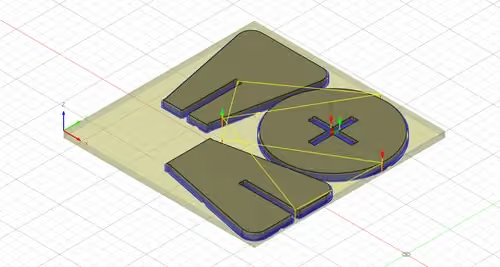
Learn how to design a parametric stool assembled with mortise and tenon and cross lap joints, then prepare its machining in Autodesk Fusion.
Xavier Klein
CNC Educator
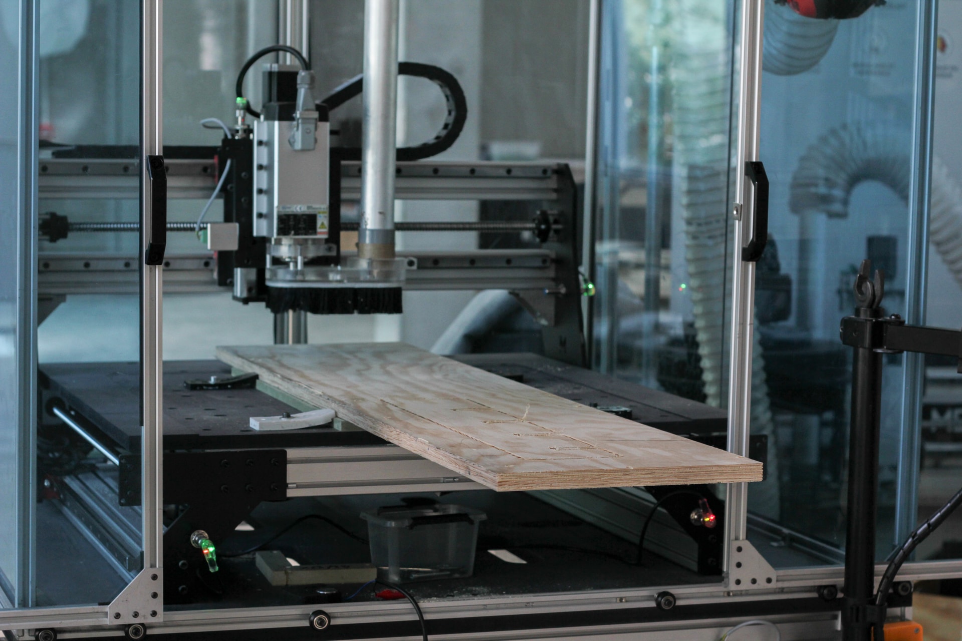
Deze handleiding leert u bewerkingen te programmeren die groter zijn dan uw machine, met de tiling-techniek. Ze behandelt CAD en CAM in Autodesk Fusion, en de bewerking zelf.
Xavier Klein
CNC Educator