Een Knikkerlabyrint Maken met je CNC
Een gids om een knikkerlabyrint van hout te maken en wat basis CNC freesoperaties te leren. Dit is een makkelijk project om te leren hoe je je CNC gebruikt.
Quentin Liard
Community Manager
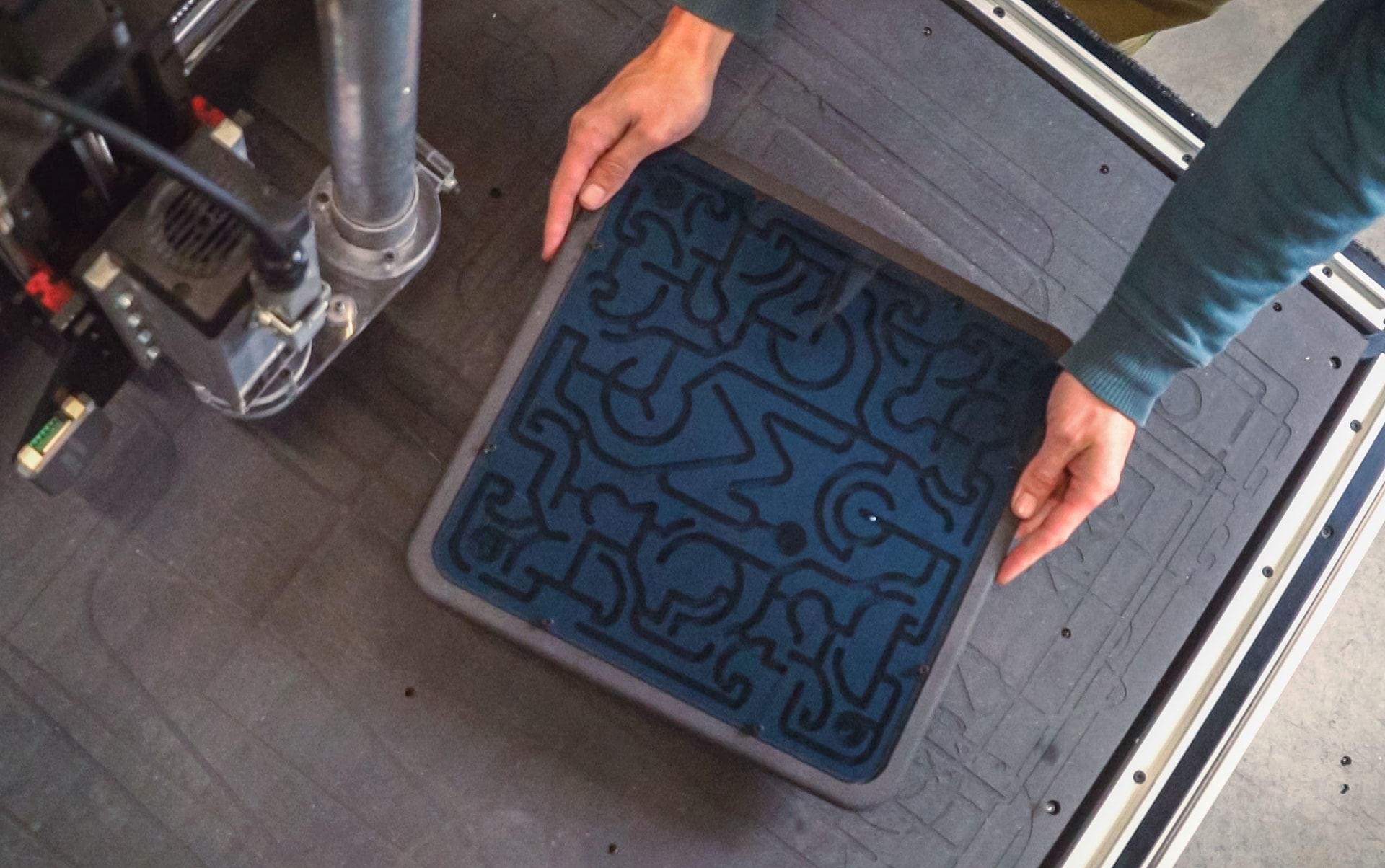
Dit project is geweldig om nieuwe mogelijkheden te ontdekken door je CNC machine maximaal in 3D te gebruiken. Het is het perfecte voorbeeld van waar een CNC machine veel preciezer is dan de menselijke hand, maar ook sneller dan een 3D printer. Het extra is dat je dit project kunt maken van elk materiaal waar een 3D printer beperkt in is.
Aangezien er bij dit project veel materiaal wordt verwijderd en precisie hier de sleutel is, is een goede klemming erg belangrijk! Om het werkstuk stevig vast te klemmen, hebben we besloten om onze voorraad rechtstreeks in de spoilerplaat te schroeven.
We raden aan om minstens 1 klem (of schroef) om de 10 cm te gebruiken om de trillingen te verminderen en de kwaliteit van je oppervlakteafwerking te verbeteren.

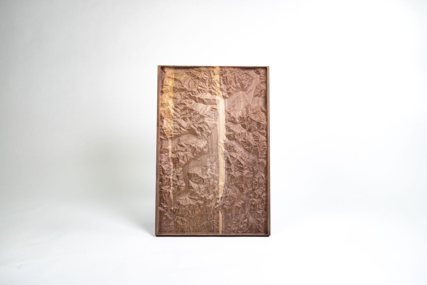
Als je geen fan bent van ons model en je wilt een andere topografische kaart frezen, kijk dan eens op deze website. Deze genereert STL-bestanden van het aardoppervlak. Deze STL-bestanden kunnen vervolgens worden geïmporteerd in Fusion360 en geschaald om te worden gebruikt als model voor het frezen.
Wij gebruikten massief notenhout voor dit project, maar je kunt elk materiaal gebruiken dat je wilt. Om onze 3D-kaart van het Comomeer te frezen, heb je een materiaal nodig dat minstens 340 x 530 x 25 mm groot is.
Vergeet niet om je materiaal aan elke kant minstens 20 mm groter te maken, zo kun je je werkstuk stevig opspannen.
Voor dit project hebben we de volgende frezen gebruikt.
Je kunt onze website raadplegen voor meer informatie over de keuze van frezen, voedingen en snelheden.
Je kunt natuurlijk ook de snijparameters aanpassen aan de beschikbare frezen.
Waarschuwing : Dit project is erg complex en heeft veel kleine details. Dit betekent dat het ook veel tijd kost om te frezen. Als je onze G-code gebruikt zoals hij is, is de totale freestijd een paar uur lang. Je kunt de freestijd verkorten door de stap over of de doorloophoogte te vergroten, maar dit zal onvermijdelijk leiden tot verlies van precisie.
Om een mooie afwerking te verkrijgen en tegelijkertijd de tijd die nodig is om ons werkstuk te maken te beperken, hebben we een G-code gemaakt die bestaat uit 3 bewerkingen.
Met een 8 mm frees ruwen we de vorm van het terrein dat we willen frezen. Door een axiale en radiale voorraad van 1 mm over te laten, zorgen we ervoor dat onze volgende frezen "iets hebben om in te bijten". Dit voorkomt dat ze wegglijden, maar zorgt er ook voor dat onze 8 mm frees de precisie van ons eindproduct niet vermindert door in materiaal te snijden waarin niet gesneden zou moeten worden.
De spindel moet worden ingesteld op een toerental tussen 20.000 en 25.000 tpm, terwijl de aanzet 3200 mm/min is. De doorloophoogte is 2,5 mm.
Om de hoeveelheid materiaal die de dunne kogelkopfrees moet verwijderen te verminderen, hebben we een eerste scallop-bewerking toegevoegd met de 8 mm vlakke kopfrees. Deze stap verwijdert het "rijstveld" effect dat overblijft na de eerste bewerking en je zult het terrein eruit zien springen. We houden 0,5 mm axiale en radiale materiaal om iets over te laten om in de kogelkopfrees te bijten.
Deze stap is niet verplicht, maar vermindert de slijtage van de kogelkopfrees aanzienlijk en stelt je in staat om de voedingssnelheid bij de volgende bewerking te verhogen (waardoor de totale freestijd korter wordt).
De spindel moet worden ingesteld op een toerental tussen 20.000 en 25.000 tpm omdat de aanzet 3200 mm/min is. De stap over is ingesteld op 3,5 mm.
Deze stap geeft al zijn textuur aan het afgewerkte stuk en laat elk detail van het terrein eruit springen.
De scallop-bewerking zorgt ervoor dat de kogelfrees in elk dal, op elke heuvel en op elke heuvelrug van onze kaart komt en zeer weinig freessporen achterlaat.
De spindel moet worden ingesteld op 20.000 tot 25.000 tpm omdat de aanzet 3500 mm/min is. De stap over is ingesteld op 0,4 mm om de hoeveelheid freessporen te verminderen.
Mekanika is een Belgisch bedrijf gevestigd in Brussel dat als ambitie heeft om lokale productie toegankelijker te maken dankzij een 100% open-source benadering.
We ontwerpen en produceren CNC frees- en zeefdrukmachines van hoge kwaliteit die een reputatie hebben opgebouwd voor betrouwbaarheid en gebruiksgemak. Onze gereedschappen worden geleverd in volledig gedocumenteerde kits, zodat ze gemakkelijk kunnen worden aangepast aan specifieke behoeften.
Bezoek onze Store om meer te weten te komen, of bekijk onze online bronnen en tutorials om verder te leren.
Een gids om een knikkerlabyrint van hout te maken en wat basis CNC freesoperaties te leren. Dit is een makkelijk project om te leren hoe je je CNC gebruikt.
Quentin Liard
Community Manager
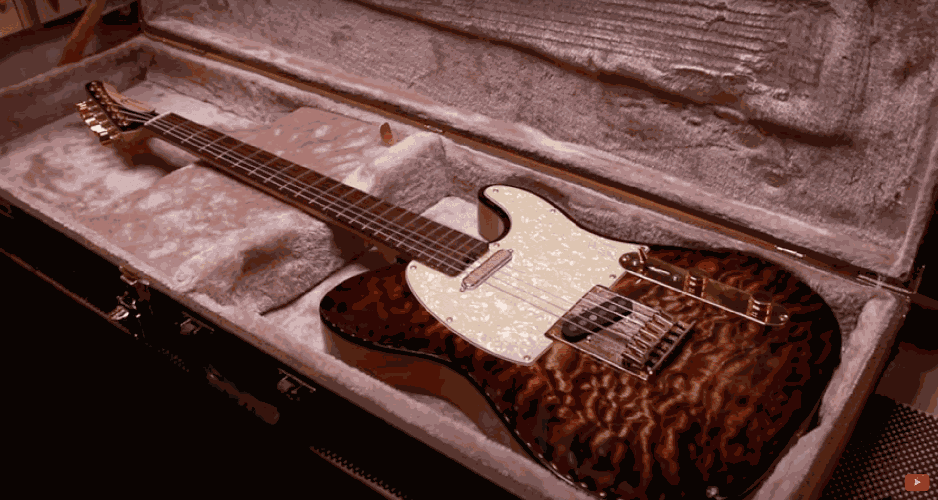
Deze gitaar is bedacht en ontworpen door Hussein van Barada Guitars, met de hulp van zijn vriend Austin, die zijn expertise leende voor het ontwerp van de CAD-bestanden.

Roldan Descamps
CEO
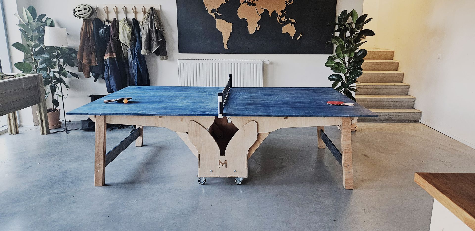
Dit project begeleidt u bij het maken van een volledig functionele opvouwbare pingpongtafel die volledig is gemaakt van CNC-gezaagde houten panelen.
Quentin Liard
Community Manager