Carveco is an accessible CAM software that is easy to learn and will get you milling your first pieces very quickly.
In this tutorial, we're going to go through the toolpath creation process in Carveco Maker (the most basic version of Carveco) in order to mill our usual tutorial clamp as an example. By the end of this article, you should be familiar with Carveco's CAM interface and basic functions, and how to use it with your Mekanika CNC machine.
Interface Overview

- Menus, Shortcuts and View selector - Main navigation controls
- Drawing tools - Vector creation and editing tools
- Global display - Shows your drawings, toolpaths, etc.
- Project content window - Contains the Toolpath menu, opened by clicking on Toolpath on the right. It contains all the CAM interfaces of the software, including operation programming, toolpath display and simulation management.
We will focus on the Toolpath window as in the context of this tutorial, we'll import our clamp *.DXF file directly, without drawing it from scratch.
You can find the file here.
If you wish to learn the basic concepts of CNC milling, we'd suggest you go through our tutorial series first before following this specific tutorial for Carveco.
Creating a New Model
Let's start by creating our new project.
Click on New Model and enter the dimensions of your stock in which we will cut our clamp, in our case it is 150 x 150 mm.

Importing the Design
We can now import the drawing of the clamp.
Click on the menu Vector > Import, and select the .dxf file of the clamp (link above).
A window opens showing you the details of the .dxf file.
Don't change anything here and keep "auto. rejoin vectors" checked.
Then click OK.
The drawing is now imported and Carveco centers it automatically in your file.

One last step: In order to be able to mill the slot at the tip of the clamp, we will draw a rectangle defining the area to be milled halfway through to create that slot (as Carveco does not understand the milling of open paths).
- Select the rectangle tool (in the toolbar on the left)
- The parameters for rectangle creation are shown on the right panel
- Enter values Width 50mm and Height 15mm and click on Create

We now need to place this rectangle above the slot.
- Go back to the Arrow (selection) tool from the toolbar
- Place your mouse above the middle of the top line of the rectangle until a special icon appears (see picture), meaning you're going to move the rectangle with the middle of this line as a reference point

- When the icon has appeared, drag and drop the rectangle downwards, above the line marking the limit of the slot at the tip of the clamp (shown in green here)
- Hold the click until it snaps to the slot's line and the same icon appears again, showing you that you are aligning the middle of the rectangle to the middle of the slot
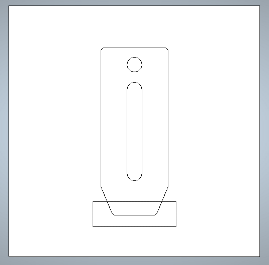
Your drawing is now ready for the CAM preparation and should look like that:

Open the toolpaths menu of the project, on the right side of the screen.
The toolpaths menu appears underneath.

We can see in this menu all the tools around CAM:
- Toolpath Operations - Menus for general parameters (such as the material, the tool library and setting tabs...)
- 2D and 3D toolpaths - To create various types of milling operations
- Simulation button - To check the toolpaths created
Let's start setting up our material (stock) specifications.
Click on "Setup Material" and enter the material thickness (for us 12mm) and set the model position in material to bottom (this means our Z0 will be set on the spoiler board, to be sure the cut goes all the way through).
The software automatically sets the top and bottom offset.

First Operation: Slot Cutting
Now we can start creating the operations. First we will cut the slot at the tip of the clamp.
- Select "Create area clearance" (which is a pocketing operation) in the 2D toolpath menu and select the rectangle we created to tell which area we want to be cleared
- Set the Start depth to zero (this is the top of the stock)
- Set the Finish depth to 6 mm (we want this slot to be 6mm deep)
We will now need to select a tool for the job.
- In Tool List click on "Add" which will open the Tool library
- Navigate to metric tools > for wood > 2D finishing and select the 6mm End Mill
The native parameters of Carveco for this tool correspond to our needs in this case, but just to check the menu, click on Edit and you'll see how you can edit the specifications, feeds and speeds of the tool here.
You can create and save copies of tools with different parameters in this library if you plan to reuse the parameters often.
- Click OK to save the tool and then click select to select it for the pocket operation we were working on
- Choose the "Offset" clearance strategy to have a continuous spiral movement
- Check the Add Ramping Moves box, as it allows an easy entry into the material instead of plunging straight into it (end mills are made to cut while moving, not straight down). You can keep all the default parameters
- You can now give a name to the operation at the bottom
- Then click Calculate Now
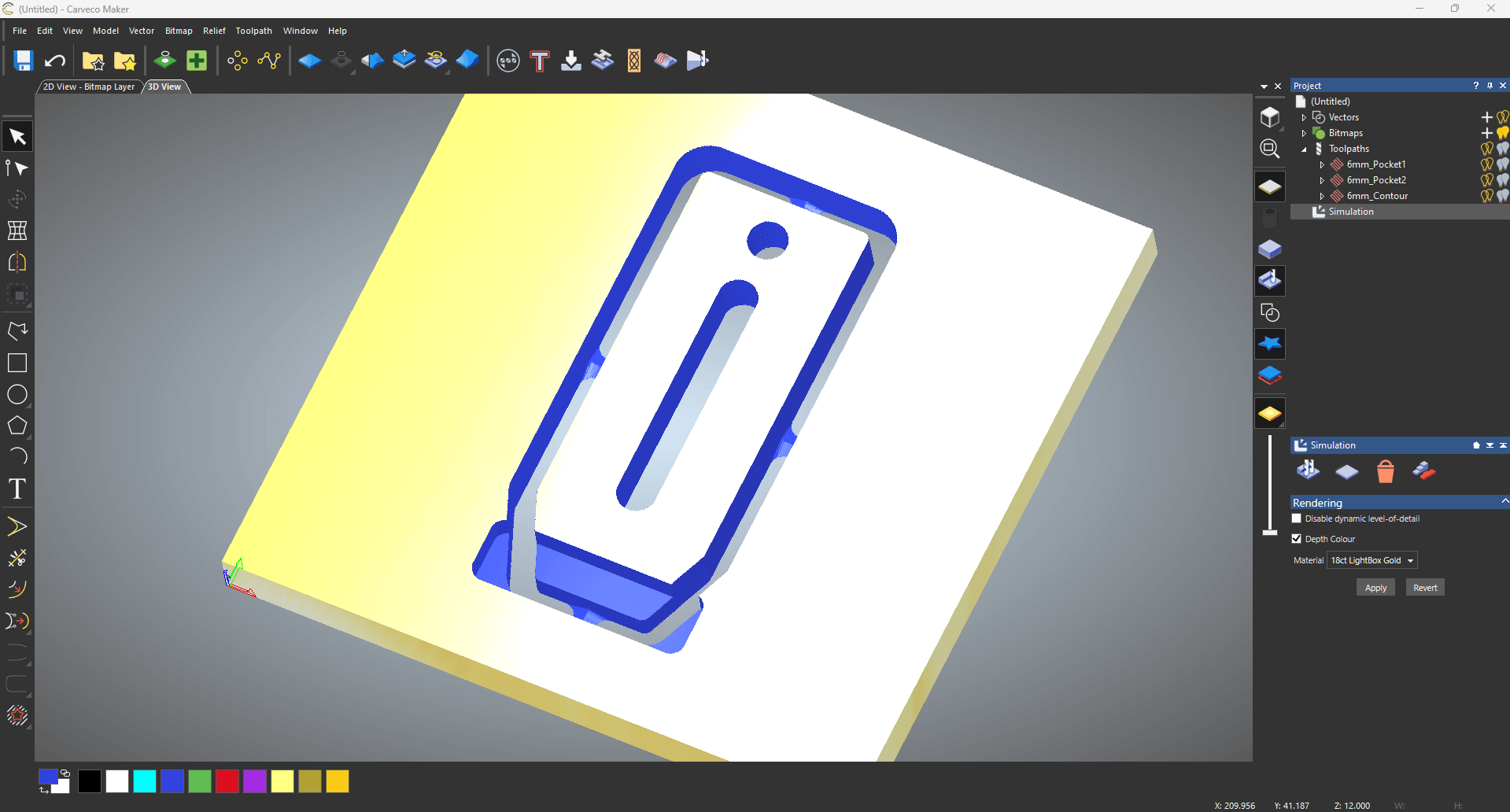
You can now switch to the 3D view (top left of the view) and see the toolpath displayed. You can also use the simulation menu on the right to have a preview of the toolpath result.

Second Operation: Holes and Groove
Let's program the rest of the operations. The next operation is also a pocket toolpath for the hole and the groove:
- Go back to the 2D view (button at the top left) to see the drawing again, and select the 2 holes by holding shift
- This time the Finish depth is 12mm deep (we want to cut all the way through) but all the other settings are the same
- The previous tool is automatically selected so no need to open the tool library
We can see we now have 2 toolpaths in the list of the project on the right.

Third Operation: Profile Cut
The last toolpath is the outline of the clamp:
- Go back to the 2D view and to the toolpath menu
- Create a Profile Toolpath in 2D Toolpaths, and select the outline of the clamp as the reference
- Select Outside of Selected Vector (so that the tool runs outside of the shape)
- Final depth must be 12mm too (the stock thickness) as we want to cut through
- We will use the same tool
- Check the box for ramping moves
- Check the box to Add Bridges
In order to avoid the clamp moving when the cut is over, this will add some tabs to hold it to the remaining stock. You can set their size, the default 5x2mm is good for a plywood clamp.
If you are not very experienced, adding 4 tabs is recommended for secure holding of the finished part.
- Set it to Auto add bridges, constant number: 4
- Then click Add to create the bridges
You can see their position may not be very logical - we want one tab in the center of each side.
- Click on Edit Bridges (Manual) and slide them to a decent position

- You can now name it and click Calculate Now.

All the toolpath are now done !
Your file is ready to be exported and sent to your machine.
Export your G-Code
A good practice is to simulate your full job before exporting anything to your machine, to see if it all seems like what you expect.
You can use the Simulate function of Carveco for that.
When you have checked the simulation and everything seems right, we're now ready to export our G-Code file.
- Click on the toolpaths menu and on Save Toolpath
- Check that all the 3 toolpaths are "to save..."
- Important: In Machine File Format, select LinuxCNC_Arc_MM_TC (.ngc)
This is the post-processor adapted to Mekanika CNC machines. If you use another machine, check with the manufacturer which post processor should be used.


- Save to your USB key, to transfer it to your Mekanika CNC
Mill your Part
We have another tutorial on how to use your Mekanika machine for the first time when you generate your G-Code, that you can find here and that is adapted to any software.
Congrats! You are now able to cut your own parts using Carveco!