Understanding & Optimizing Your Vacuum Table
Find out how to maximize the performance of your vacuum table by learning practical tips on cutting strategies, spoilerboard maintenance and many more.
Maxime G.
Product Engineering

Understanding how feeds and speeds work is critical if you want to improve your CNC skills. It will help you to optimize your machining speeds, to obtain a better surface finish and most importantly to have a longer tool life.
If you're using end mills that you bought at Mekanika, you can access the pre-configured feeds and speeds for Autodesk Fusion 360 here.
Hence, getting your feeds & speeds right simply means finding the sweet spot where your tool is spinning at the perfect speed relative to its moving speed inside the material.
That sweet spot can mean different things depending on your goal: achieving the best surface finish, machining your parts the fastest, or maximizing your tool life.
These concepts can be visually summarized on a graphic, where the feedrate is plotted against the spindle rotational speed, and which helps us to identify 6 different zones.
As illustrated above, there are mainly two bad spots that you want to avoid. The first one happens when you reduce your spindle speed too much relative to the feed rate. Doing so, you're forcing the flutes of your end mill to cut off too much material, which can lead to unwanted vibration or worse, a broken tool.
On the other side of the graphic, if you reduce the feed rate too much relative to spindle speed, the flutes of your end mill will start rubbing the material instead of cutting nice chips.
This action will make your tool overheat, and thus soften. Its sharp edges will become dull and if you keep cutting with dull edges, you will start to see a very deteriorated surface finish on your material.
A good rule of thumb is to always remember that you need to make chips, not dust.
The question is now: how do we find the sweet spot for any given material?
The parameter that links these concepts and that is widely used as a standard metric to determine optimal feeds & speeds is called chip load.
Chip load, also called "feed per tooth", is the thickness of material that is fed into each cutting edge as it moves through the work material.

Chip load is expressed in mm/tooth and can be found using the following equation:
Feedrate = N x Chipload x RPM
where N is the number of flutes of the end mill and RPM is the rotational speed of the spindle.
Let's illustrate this concept and imagine you want to cut plywood with a 6mm 2-flute end mill. In our case, the recommended chip load for plywood is around 0.1mm/tooth (cf. the Advanced chip load table at the end of this article).
Let's define an arbitrary feedrate of 2 000 mm/min. Using the former equation, we find that the spindle has to rotate at 10 000 rpm to achieve the proper chip load:
2 000 = 2 x 0,1 x 10 000
Based on this mathematical relation, we observe that if we want to increase the feed rate to cut that plywood faster, we will have to increase the spindle rotational speed as well to keep a constant chip load :
4 000 = 2 x 0,1 x 20 000
Now let's imagine that your spindle can't run faster than 10 000 rpm. We can still increase the feed rate by using a 3-flute end mill and keep a constant chip load:
3 000 = 3 x 0,1 x 10 000
Based on this knowledge, we can now use tables that will allow us to calculate our feeds & speeds and achieve an optimal chip load for any given material.
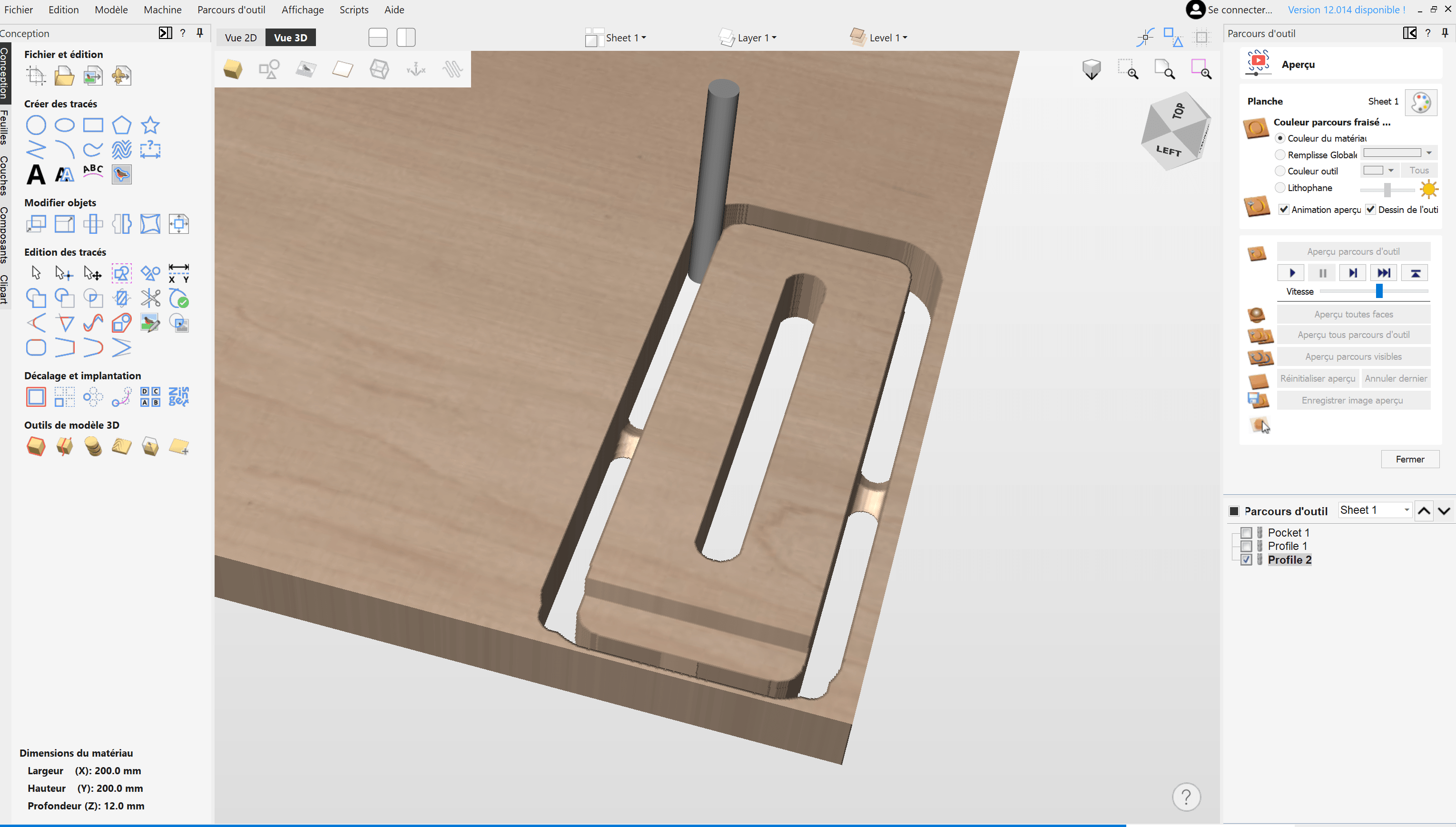
Feedrates are found using the formula given earlier in this document, but Fusion 360 embeds a very handy chip load calculator which gives you the mill's chip load for given feed and speed.
This tool allows you to tweak your feed and speed while keeping an eye on the chip load. Or the other way around: to enter a chipload and either a feed or speed, to obtain the third value automatically.
If you are not yet familiar with your machine, we compiled a starter chip load table with lower values. They are intentionally low to help you get confident with the machine no matter the type of engagement, the hardness of your material, etc...
|
Materials |
Beginners reduced Chip Loads for various tool diameters [mm/tooth] |
||||
|
2mm |
3mm |
4mm |
6mm |
8mm |
|
|
Hardwood |
0,02 |
0,04 |
0,06 |
0,08 |
0,1 |
|
Plywood |
0,03 |
0,05 |
0,06 |
0,08 |
0,09 |
|
MDF |
0,04 |
0,05 |
0,06 |
0,09 |
0,1 |
|
Soft plastics |
0,05 |
0,07 |
0,08 |
0,1 |
0,12 |
|
Aluminium |
0,01 |
0,02 |
0,02 |
0,03 |
0,04 |
An important factor to consider while reading these tables is the tool diameter. A larger end mill will indeed be able to handle a larger chip load.
Here's a chip load table for when you acquired enough confidence to run more optimized feed rates. (values in mm/tooth)

As stated earlier in the article, we recommend that you start by setting the actual feedrate of your machine below the value from the table and gradually increase it. In general, you will find that your optimal feeds & speeds will be determined from experience and trial-and-error.
For instance, for most materials, you can typically set the spindle speed between 15,000-25,000 rpm and adjust your feed rate to obtain nice results with your machine.
Similarly, we suggest you slowly increase the depth of your cuts while doing these tests. Indeed, excessive depth of cut will result in tool deflection (see this article to understand why that can be problematic).
Most CNC users actually use experience to determine the depth of cut value for a particular situation.
Before diving into numbers and values, you need to be aware that the following variables will heavily influence the quality of your cuts and the achievable chip load on the same machine.
Always clamp your workpiece in the best possible way. A loose workpiece will vibrate while being cut and cause a bad surface finish.
If you are not sure about your clamping, use wood screws to attach your workpiece in many points to the spoiler board. It is not the fanciest method, but it is fast and efficient.
The harder the piece, the more deflection your end mill will bear.
This will cause chatter and vibrations. Be patient when milling hard material and use smaller steps or lower your feedrate.
An end mill is a cutting tool and with time, it will eventually get dull. As it gets worn out, you will need to take it easier and reduce the feedrate to keep a good surface finish. You can also just replace it or resharpen it.
Depending on how deep you want your end mill to go inside the material, you will have to adapt your feed rate to spare it.
A general rule of thumb for beginners is to take passes with a maximum depth of cut around half the diameter of your tool.
The advanced rule for high grade CNC being: maximum depth of cut = tool diameter.
But remember, as mentioned above: some more complex or hard materials require lower depth of cut (typical examples are aluminium and Plexiglas...), and some softer materials or some less agressives operations may allow bigger depth of cut.
But if you want to be safe in most of the cases, just remember:
Maximum depth of cut = ½ tool diameter.
During some milling operations, more than ¼ of your tool's circumference "touches" the material during the milling. As a result, the end mill can't cool down properly and tends to overheat easily.
So again, for these heavier milling operations, you will need to use a lower feedrate to allow your mill to stay cool, or simply reduce the depth of cut.
|
Light engagement |
Heavy engagement |
 |
 |

As you can see in those tables, the type of material milled can have a great influence on the chipload goal, and on the milling strategies.
To help you, we have built a library of the most common materials used in 3-axis CNC milling machines to help beginners gand give tips about the specificities that each material presents.
We propose advices corresponding to each of our Mekanika machines, but they can be applied to any other brand.
Along side the Feed & Speed Calculator for beginners found below, you should get enough information to get started milling any kind of materials.
Although the theory behind calculating an optimal chipload is straightforward (and there are plenty of online calculators to help you avoid doing it by hand), the reality often differs from the theoretical values.
To help you find a starting point when milling new materials, we have created a Beginners' Feed & Speed Calculator that will suggest conservative and 'safe' values corresponding to your machine, tool and material. This means you can start with these values and increase them progressively to find the optimal parameters.
BUT REMEMBER: many factors can influence the optimal feed/speed, such as machine rigidity, material type and fixation, depth of cut, end mill type and condition, and the required surface finish... So don't blindly use any calculator's values: always use your common sense and experience to adapt them if needed.
Mekanika is a Belgian company based in Brussels whose ambition is to make local production more accessible thanks to a 100% open-source approach.
We design and produce high quality machines for CNC milling and screen printing, which have been recognized for their reliability and ease of use. Our tools are delivered as kits and fully documented, allowing to easily adapt them to specific needs.
Visit our shop to find out more, or check out our online resources and tutorials to continue learning.
Find out how to maximize the performance of your vacuum table by learning practical tips on cutting strategies, spoilerboard maintenance and many more.
Maxime G.
Product Engineering
Learn how to create your project and generate G-Code from VCarve Pro or Aspire to easily machine your parts on a CNC milling machine.
Xavier K.
CNC Training
Hot engraving, cold engraving, tools and tutorials: everything you need to know about wood engraving with your CNC machine.
Quentin L.
Content Creation