This guide will enable you to program machining operations larger than your machine using the “Tiling” technique. We cover both the CAD and CAM aspects in Autodesk Fusion as well as machining.
Xavier Klein
CNC Training

Making large and/or complex projects can be quite challenging as there are often multiple pieces intersecting each other in multiple directions.

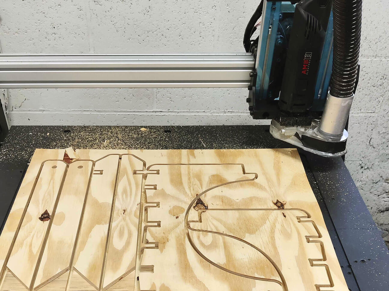
In this article we’ll introduce you to the nesting technique and the 2 different ways to make your CAM file for complex projects like this sled.
We have already mentioned it, clamping your stock to your spoilerboard can be a hassle (at least if you don't own a vacuum table).
Fortunately, there is a good way to minimize the amount of times you spend switching from one piece to another while limiting material waste: it's called nesting.
The concept is pretty straightforward: basically, nesting consists in organizing on the same stock the different elements you plan on milling with your CNC machine so that you minimize the space between each of them.
This way you can mill them all at once while optimizing your material use.
Arrange method is only available for commercial license
If you are using a commercial license of Fusion360, you have access to a tool that will change your life when it comes to making large projects: the “Arrange” function.
This function allows you to put multiple components flat on a plane with needed spacing between them (to allow an end mill to pass), while optimizing every cut according to the stock you have available.
It goes even further as Fusion360 will automatically go from a flat layout in the “Manufacture” environment to the “finished assembly” layout in the “Design” environment.
Design View |
Manufacture view |
 |
|
In order for the Arrange function to work, every item has to be a Component. It will not work with bodies. To change a Body into a Component, right-click on the body in the side menu and select “ Create Components from Bodies”.

1. In the Manufacture environment, go to the “Setup” menu and click on “Create a Manufacturing Model”.

This will give you access to a new environment where you will be able to change the position of your component without affecting the original model.
2. To access that environment, right-click on the manufacturing model in the side menu and select “Edit Manufacturing Model”.

For projects that require multiple stocks of material, we recommend creating multiple manufacturing models (1/stock). To help you visualize which pieces already have a dedicated model and which don’t, you can hide pieces that already have a model. This way, you’ll end up with multiple models each having specific parts visible which should help you to avoid milling the same part multiple times or forgetting one. 3. In this new environment, new tools are displayed. The one we are looking for is in the “Modify” tab and is called “Arrange”.

If you are running an older version of Autodesk Fusion 360, you might want to check out this page if you’re struggling to find the “Arrange" function.4. Now select the desired components and the plane you want to place them on. Enter the dimensions of your stock. In our case, the sled was made on our EVO-S CNC machine which has a working area of 650x650 mm so we made sure the stock would fit into these dimensions.
Adapt the borders and spacing according to your milling setup and click OK.

5. We can now use the Manufacturing model we just edited to set up our milling as usual.
If you are using the free version of Fusion360, you don’t have access to the previous method. But you can however achieve a similar result with a little extra labor.
1. Follow the same steps as in the previous section to create a manufacturing model.
2. Inside that model, Use the “Align” function to place all components on the plane of your choice.


3. On that plane, create a sketch and make a rectangle that has the same dimensions as the stock you are planning to use.
4. Go to the top view and capture the position of your components.
5. Now drag and drop or move all the components so they fit inside the stock you’ve drawn.

Though this method takes more time, you can achieve a very decent flat layout without needing a commercial license.
Mekanika is a Belgian company based in Brussels whose ambition is to make local production more accessible thanks to a 100% open-source approach.
We design and produce high quality machines for CNC milling and screen printing, which have been recognized for their reliability and ease of use. Our tools are delivered as kits and fully documented, allowing to easily adapt them to specific needs.
Visit our shop to find out more, or check out our online resources and tutorials to continue learning.

This guide will enable you to program machining operations larger than your machine using the “Tiling” technique. We cover both the CAD and CAM aspects in Autodesk Fusion as well as machining.
Xavier Klein
CNC Training

Planet CNC offers the option of starting a G-code from a specific line instead of from the beginning. This can be useful for resuming a job that was stopped for various reasons, such as a program/computer crash, a power outage or an emergency stop.

Quentin Liard
Customer Support

Find out how to maximize the performance of your vacuum table by learning practical tips on cutting strategies, spoilerboard maintenance and many more.

Maxime Gravet
Product Engineering