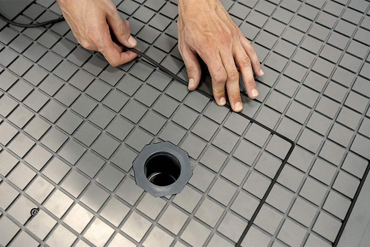
For reasons of space, budget, or simply usage, you have opted for a small-sized machine. However, you may sometimes want to machine parts that are larger than your machine's workspace, which can be frustrating. Fortunately, there are techniques to get around this physical limitation by properly preparing your file in Autodesk Fusion. This technique is called "tiling".
Like always with Fusion, the procedure presented here is certainly not the only one possible.
We will assume that we are working on a Mekanika Pro S with a 600x600mm workspace. We also assume that you already know how to prepare simple machining operations on Fusion.
Note that Vectric's VCarve has a dedicated tiling function located in the Toolpaths panel, but you have to draw the positioning holes yourself :

The Part & General Principles
Here, we will use the dimensions of a fictional shelf measuring 1100 mm long by 100 mm wide. You can use our example by downloading the file here or by using one of your own drawings.
You will therefore need a stock that can welcome your machining and possibly a "fake spoilerboard" if you don't want to machine directly into your spoilerboard.

The principle will be to draw and mill 2 holes in order to plug 2 tenons.

Once this is done, we can start milling our part using the usual operations. The trick is to limit these operations to our workspace. With each new machining operation, we will mill two more holes in the stock, which we will use to position it for the next operation.

Then we move the stock and place it with the 2 holes:


And we do this until we have machined the entire part.

So we need to draw the stock, the tenons and the rectangles to confine our toolpaths.
Preparation for Machining in the Design Workspace
Drawing the Stock and Positioning Holes
Create a new sketch and position it on the XY plane.
Draw a rectangle around our object representing the 1245x285mm stock. You can also adjust these values if you already have a suitable stock.

At the bottom of this rectangle, we will draw two circles.
These circles will be used to machine the holes for the placement tenons. The ones we will use here are 7 mm in diameter, so we will make 7.2 mm holes.

Select the Create > Sketch Dimension tool, click on the circle on the left, then on the horizontal line on the bottom. Place the dimension and enter 10 mm to set the distance between the two. Do the same with the vertical line on the left, then on the second circle on the right:
 Select Create > Rectangle > 2-point Rectangle. Click on the lower left point of the large rectangle and enter the dimensions 550 mm high and 200 mm wide. This rectangle will be used to define the first machining operation, which is why it measures 550 mm high, slightly smaller (to allow for margin) than the 600 mm limit of the Mekanika Pro S:

Draw a new rectangle with the same dimensions. Place the first point below the top of the first small rectangle so that the two rectangles overlap. This overlap allows the machining operations to also overlap and ensures that they join together:

Set this overlap to 10 mm using Create > Sketch Dimensions, then clicking on the top side of the first bounding rectangle and then on the bottom side of the second bounding rectangle.

Repeat these two operations until the end of the shelf:

We will now draw the positioning circles for each boundary. Draw two circles above the overlap of the two rectangles and use Create > Sketch Dimensions to position the circles 10 mm from each side. For the vertical dimension, use the line at the bottom of the overlap:

Repeat the process for the other two parts.

You can finish the sketch.
Stock Extrusion
Hide the body representing the part and extrude (Create > Extrude) the stock to the same height (here 18 mm). Select everything except the holes.

Displays the sketch of this last extrusion as well as the body of the part to be cut.

You can switch to the Manufacture workspace.
Machining Setup
First Setup Configuration
As always, start by clicking Setup > New Setup. Define the origin point of the working coordinates to the lower left corner of the part:

In the Stock tab, enter 0 mm for each Offset settings :

Click on Ok to confirm the Setup. If this message appears, click on Yes.

First Operation: Boring in Stock and Fake Spoilerboard
Select 2D > Bore. We won't go into detail here, but we will point out the specific steps to follow to create the operation:

- Choose your milling cutter, its diameter must be smaller than the hole you want to make. Here, we have a 7.2 mm diameter hole, so we will use a 6 mm diameter milling cutter. It is best to use an upcut milling cutter to pull the chips upwards and prevent clogging during machining.
- In the Geometry tab, select only the first two holes (those closest to the origin point).

- In the Height tab, add an offset of -7.5 mm to the Bottom Height value. This allows you to drill deeper to pierce both the stock and the fake spoilerboard. Adjust the offset value to the thickness of your fake spoilerboard and the length of your tenons. Just make sure that the length of the cutter is sufficient to bore all the way to the bottom without risking collision with the spindle collar.

- In the Passes tab, check that the Angle value is set to 35 deg (refers to the ramp angle).

You can click on OK to confirm the operation.
Boring of the Following Holes
Program a second bore, this time for the next two holes. They must not drill into the fake spoilerboard.

First 2D contour operation
Use the Browser to hide the stock.

Select 2D > 2D Contour:
- Select your bit.
- In the Geometry tab, select the lower contour of the part.

- Add tabs, use plenty of them and make sure they're thick. This is because the piece may have to be held slightly in mid-air, and there is a risk that they may break.

- Click on Stock Contours and select the first bounding rectangle (remember to keep the sketch visible). This option allows you to define the cutout within this perimeter.

- Don't forget the Passes in the appropriate tab (remember: Maximum Roughing Stepdown) and in the Linking tab, uncheck Lead-In (Entry) and Lead-Out (Exit). Do not check the Ramp option. We uncheck these options to prevent strange movements due to the delimitation of the tool path. Therefore, be careful if you are using a tool that requires a ramp approach.

Once the configuration is complete, observe how the machining stops at the boundary rectangle.

Remaining Machining
Now we need to repeat the last two operations (the second boring and the 2D contour) by modifying the working coordinates each time.
Create a new Setup, this time in the Work Coordinate System (WCS) section, and select Selected Point from the Origin menu:

Then click on the left corner of the second bounding rectangle.

Then validate the Setup, configure the bores and then the 2D contour of the second part:


You can then continue for each part, moving the working coordinates each time.

Post-Processing
Export each Setup separately, naming them clearly so you don't get confused when you're at the machine:

Machining and Installation of Placement Tenons
Place the fake spoilerboard and measure the size of the cutter by placing the Z sensor on it.

Then place the origin of the working coordinates, avoiding being too close to the limit on the Y axis. This is because some paths may exceed the physical limits of the machine, in which case machining will be stopped.

Position the stock: we start at the bottom, with the rest overhanging at the rear of the machine.


We will use screws in this example: be careful not to position them in the path of the milling cutter!
Then start the first machining operation, beginning with the deep bores and continuing directly with the bore+2D contour pair.


Remove the stock from the fake spoiler board and note the two holes that have been machined:


Place the tenons in these holes:


Replace the stock on the martyr, using the second pair of holes as a guide:

Secure the stock with the screws:


Do not change the working coordinates!
Start the second machining operation. If all goes well, this will cut the shape without any offset.

This is when it is important to have placed numerous, sturdy tabs: the first part of the machining process takes place outside the cutting area, and without these tabs, the part can vibrate very strongly.

Once finished, simply move the stock forward and start the third operation. Place the stock on the third pair of positioning holes. Repeat these instructions as many times as necessary!

There you go! If all goes well, the part is machined correctly, without any misalignment.


Conclusion
Now you know how to machine an object bigger than your machine! Although we have moved our part on the Y-axis here, it is entirely possible to do so on the X-axis.
This tutorial is largely based on the excellent videos by Jonathan Katz-Moses and Aribabox. We mainly sought to simplify and streamline a few techniques, so thank you to them!
How To Cut Parts Bigger than your CNC Bed with Fusion 360
Making Large Parts on a Hobby-level CNC Router - Tiling Tutorial with Fusion 360


 Select Create > Rectangle > 2-point Rectangle. Click on the lower left point of the large rectangle and enter the dimensions 550 mm high and 200 mm wide. This rectangle will be used to define the first machining operation, which is why it measures 550 mm high, slightly smaller (to allow for margin) than the 600 mm limit of the Mekanika Pro S:


