VCarve Pro is a trusted CAD and CAM software made specifically for CNC milling.
It is easy to learn and will get you to mill your first pieces very quickly. Its bigger brother Aspire is an enhanced version adding 3D modeling to the functionalities.
In this tutorial, we’re going to go through the CAM section of VCarve Pro (as Aspire has basically the same) in order to mill our usual tutorial clamp. By the end of this article, you should be familiar with VCarve CAM interface and basic functions, and how to use it with your Mekanika CNC Machine. Here's the structure of the article
- VCarve Overview
- Setup machine and post processor
- Importing the design
- Toolpath creation and End mills library
- Export your G-code
- Mill your part
1/ VCarve Pro Overview
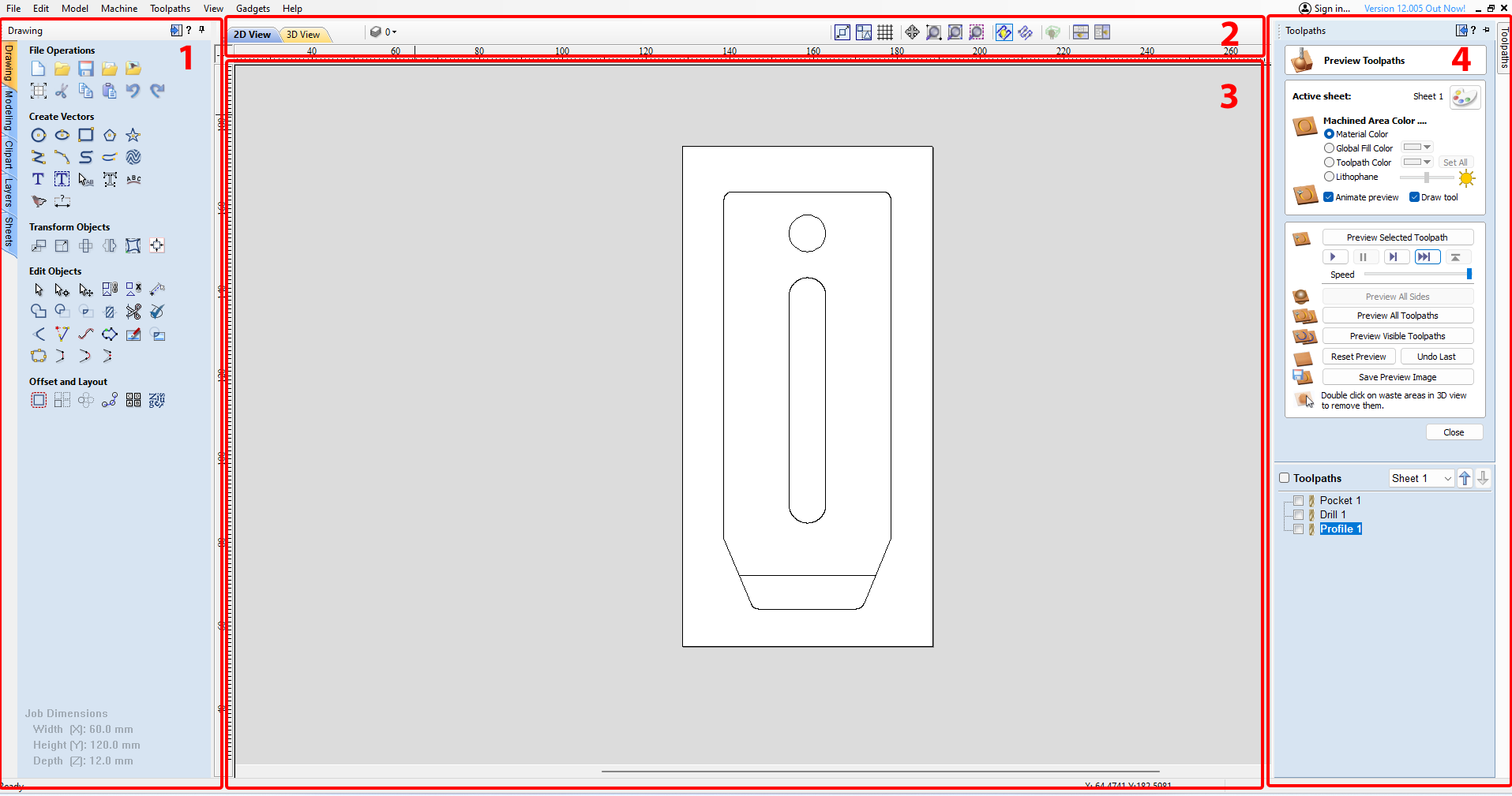
- Design workshop selector and tools, that you can switch with the tabs on the left (depending on what you want to create/import/edit). Each workshop has different tools, but the main tab will be "Drawing" and we will only use this one here.
- View toolbar that allows you to switch between 2D and 3D view, hide/show layers, select parameters for the behaviour of the global display panel etc.
- Global display, showing your drawings, toolpath, etc.
- Toolpath window that can be opened by clicking on the tab on the right. It contains all the CAM interface of the software, including operation programming, toolpath display and simulation management.
We will focus on the Toolpath window as in the context of this tutorial, we’ll import our clamp *.DXF file directly, without drawing it from scratch.
If you wish to learn the basic concepts of CNC milling, we'd suggest you go through our tutorial series first before following this specific tutorial for Vcarve.
2/ Setting up the machine
and post-processor
Before starting, we will enter the parameters of your machine and import Mekanika's post-processor to generate G-Code that the machine will understand.
Go on the Machine menu at the top and select either Machine configuration or Add a machine if you are using various CNCs :
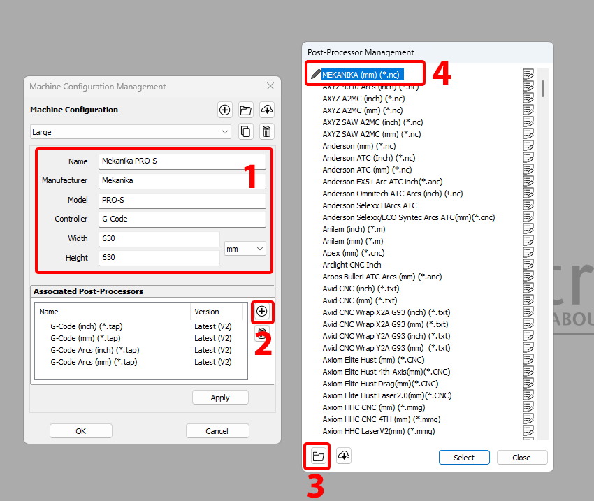
- Enter the parameters of your machine working surface and give it a name
Here I am doing it for a Mekanika Pro S. Make sure to use mm and not inches. - In the associated post-processors window, you can remove all the pre-listed ones with the trash button. Then click on the + button to add our own.
You can download the Mekanika VCarve post-processor file here - Click on the folder button at the bottom of the Post-Processor Management window to import a file. Navigate to your downloaded file and import it.
- Select the MEKANIKA (mm) Post Processor and validate, then validate the machine configuration
3/ Importing the design
We will start by importing our .dxf file of the clamp model:
Create a new file in File > New
First we are asked to enter our Job setup:
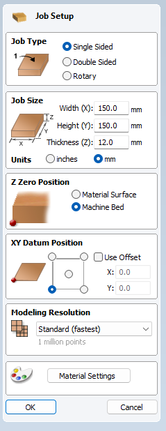
- Our Job type is single sided (we will mill only on one face)
- Our Job size will be the size of the stock material we will use, and its thickness.
Make sure to enter your own values if they are different. Thicnkess must be as precise as possible (measure your stock) and width and height must be bigger than the clamp model (100x40mm). - Z-Zero position is the place you'll put pour probe on when measuring the tool.
We recommend Material Surface if you plan to do operations not going through the whole stock thickness, like engraving.
We recommend Machine Bed if you plan to cut the stock all the way through (so i choose this one in our case as we want to cut the clamp). - XY datum position is the reference point for the working X0Y0 position
It is usual to select bottom-left. - Resolution can stay on the fastest
- Material settings is a selector for the visual aspect of the stock in the software.
- Validate with OK
_
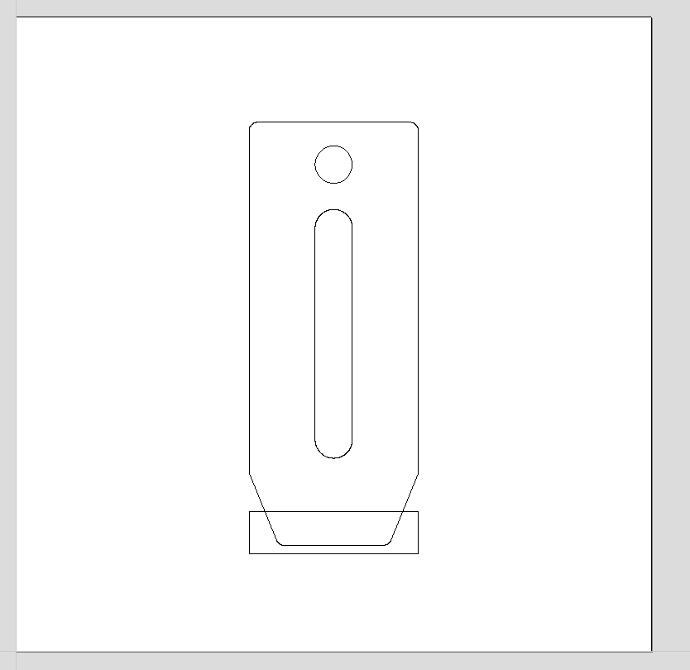
We now have all the Drawing tools available, and can import our DXF file.
Click on File > Import > Import Vectors (Ctrl/Cmd+I) and import the dxf.
You'll see it will probably be placed in a weird way on the stock. So we need to center it.
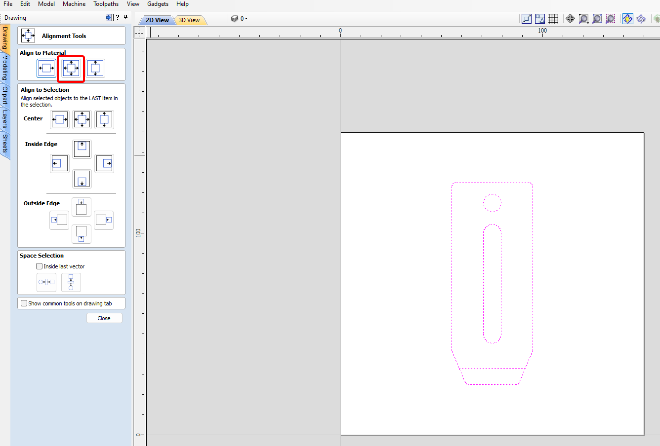
In the drawing menu on the left, click on the Align tool :
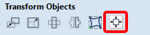
Make sure the whole drawing is selected (Ctrl/Cmd+A) the lines become pink and dotted to show the selection.
And click on Align to material center.
The drawing is now centered, you can close the Align window
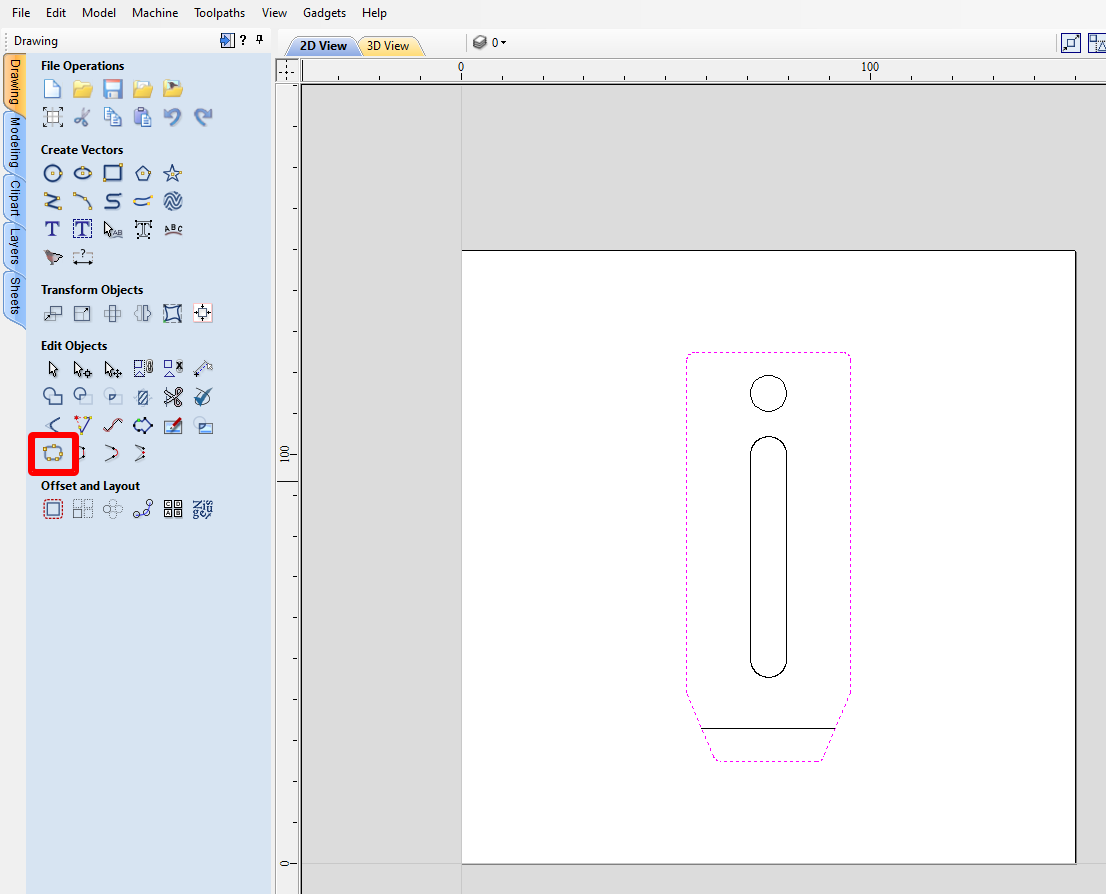
Now select all the outer lines of the clamp (make sure you don't forget the rounded corners lines) and click on Join Vectors > Join , to close the path and have a single object for the contour of the clamp.
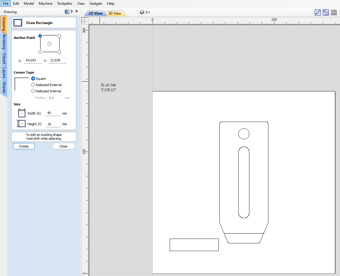
One last step : in order to be able to mill the slot at the tip of the clamp, we will draw a rectangle defining the area to be milled (as VCarve does not understand milling open paths).
Select the rectangle tool, enter values Width 40mm and Height 10mm and click anywhere in the view to create the rectangle.
Close the rectangle tool when it is created.
Triple click on the created rectangle to allow to move it freely (handles and control points appear all around the shape).
Put your mouse above the middle of the top line of the rectangle until a special icon appears, meaning you're going to move the rectangle with its middle as a reference point.
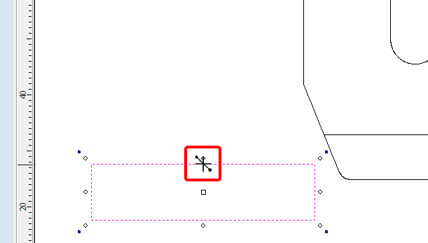
When the icon has appeared, drag and drop the rectangle above the line marking the limit of the slot at the tip of the clamp, until a vertical dotted line appears showing you align the middle of the rectangle to the middle of the slot AND a green line appears showing that the top of the rectangle is aligned with the top of the slot.
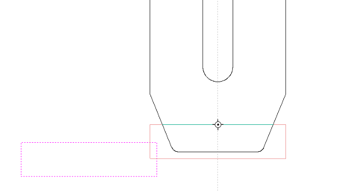
Your drawing is now ready for the CAM preparation and should look like that :
4/ Toolpaths creation and Tool library
Open the toolpaths window on the right of the screen, and pin it so it stays open.
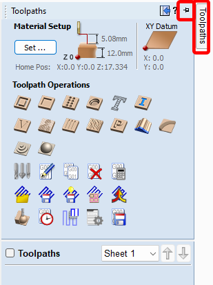
We can see in the window the different type of operations possible. There is also a Material Setup button at the top if you need to modify the parameters entered when creating the file. (There are also a few more parameters here, but the defauts are fine).
Let's start by creating the pocket for the slot of the tip of the clamp. Select Pocket Toolpath.
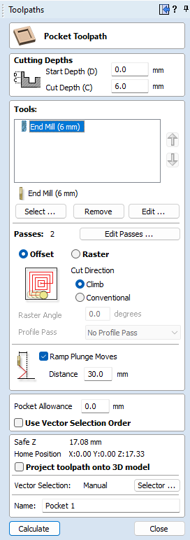
First, select the drawing that need to receive this operation, here the freshly created rectangle.
At the top you can set how deep the cut will be:
For this slot we want it to start at 0mm (at the top of the stock) and be 6mm deep.
Then you need to select the Tool for the job:
Click on Select... and browse the Tool database. You can start by hiding imperial units tools to have a clearer view. Then look for a tool describing the one you have. We recommend taking a 6mm end mill (under Metric tools > End mills) for this job.
With the 6mm endmill selected, Click on the + button at the bottom to duplicate it and adjust its settings with "create settings". Those are parameters recommended for our machines to cut plywood for the first time :
- Set the flute number to your tool's flute number (for me 3)
- Set the pass depth (the maximum depth at which every pass will be) to 3mm.
- Leave the stepover to 40%.
- Set the spindle speed to 18 000 rpm
- Feed rate to 2 500 mm/min.
- Plung rate at 1000mm/min is fine
- And tool number to 1
Click apply to save it on the tool and then click select to select it for the pocket.
You can see it automatically calculated 2 passes are needed (2 x 3mm)
Cut direction can be left on Climb
Check the Ramp box, as it allow an easy entry in the material instead of pluging straight in it (end mills are made to cut while moving, not straight).
Set the Ramp distance to 30mm.
You give a name to the operation at the bottom.
Then click Calculate.
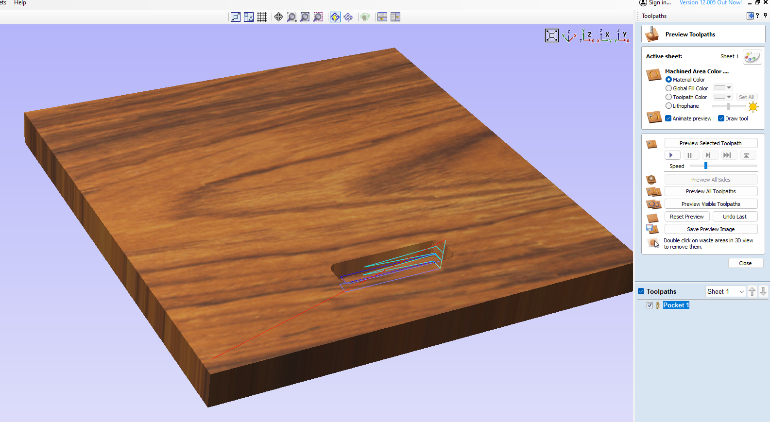
The software calculates the toolpath and automatically opens the 3D view and the simulation tool: Preview Toolpath. Here we can view the path displayed in red and blue, and can press play to see the simulation of the operation. If you are happy with the simulation, you can click close to go back to the main toolpaths window.
Now let's program the rest of the operations.
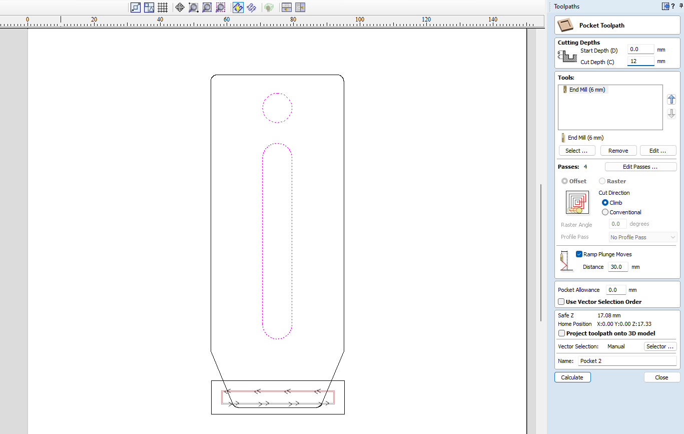
The next operation is also a pocket toolpath for the two inner holes:
Go back to the 2D view (button at the top left) to see the drawing again, and select the 2 holes. This time the cuts 12mm deep (cut through) but all the other settings are the same and the previous tool is automatically selected so no need to open the tool database.
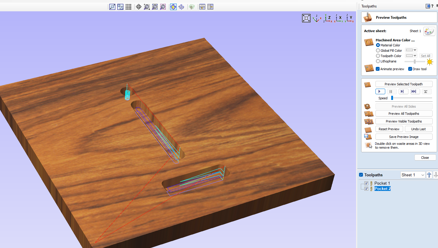
We can see we now have 2 toolpaths in the list.
The last toolpath is the outline of the clamp:
Go back to the 2D view, create a Profile Toolpath and select the outer line.

Cut depth must be 12mm too (the stock thickness) as we want to cut through.
We will use the same tool (it is automatically selected).
Select outside/right of the vector (so that the tool runs outside of the shape)
In order to avoid the clamp to move when the cut is over, we will add some tabs to hold it to the stock. Check Add tabs to toolpath. You can set their size, 10x2mm is good for a plywood clamp. Then click on Edit tabs to edit their position.
If you are not very experienced, adding 4 tabs is recommended for a secure holding of the finished part. Set it to constant number: 4, and avoid corners. Then click Add Tabs. You can see their position on each side.

Close the tab window and you are back to the profile operation.
Check the Add Ramp box, for the same reasons as before.
(Smooth and 100mm distance.)
Then click Calculate.

All the toolpath are now done !
Your file is ready to be exported and sent to your machine.
5/ Export your G-Code
A good practice is to simulate your full job at low speed before exporting anything to your machine, to see if it all seems like an acceptable machine movement.
We're now ready to export our milling file.
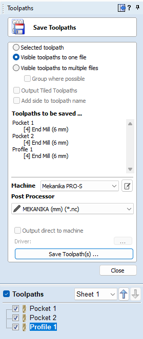
Click on Save Toolpath
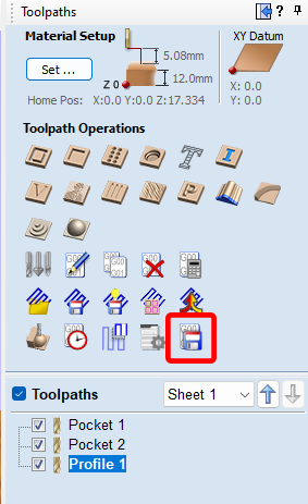
Select Visible Toolpaths to one file (as we want all the paths exported and don't need them to be split in different files).
Check that all the 3 toolpaths are "to be saved..."
Check that the Post-Processor selected is: MEKANIKA (mm) (*.nc)
And then Save Toolpath to your usb key, to transfer it to the Mekanika CNC.
6/ Mill your part
We have another tutorial on how to use your Mekanika machine for the first time when you generate your G-Code, that you can find it here and is adapted to any software you'd use with your machine.
Congrats! You are now able to cut your own parts using VCarve!