CoreDRAW is a professional graphic design suite, originally designed as a vector graphic software. It is not purposedly designed for CNC milling and does not include the usual CAD/CAM logic, but you can use it to export vector files that you will either be able to use in Fusion360, or to import directly in your Mekanika CNC machine.
In this tutorial however, we’re going to go through CorelDRAW and a new plugin called CamDRAW - available only for Windows as from December 2023 - in order to mill our usual clamp from start to finish without leaving the CorelDRAW environment. This article is intended for existing users of CorelDRAW who should, by the end of this article, be familiar with CamDRAW interface and main functions, and how to use it with your Mekanika CNC Machine. You’ll also find a section with advice on how to adapt your vectors drawings for CNC milling:
- Install CamDRAW on CorelDRAW
- Create tools in your tool library
- Create toolpaths with CamDRAW and export G-Code
- Mill your part
- Additional notes: tips on vector drawings for CNC milling
If you’re hesitating between some softwarsome software, you can compare different CAD/CAM software here to make your choice.
If you’re new to CorelDRAW and CamDRAW, you can subscribe to their services here and here. At the time of writing this article, CorelDRAW costs 369€ / year or a one-time payment of 779€, and CamDRAW costs 209€ / year or a one-time 420€ payment. Both offer a free trial period.
1/ Install CamDRAW on CorelDRAW
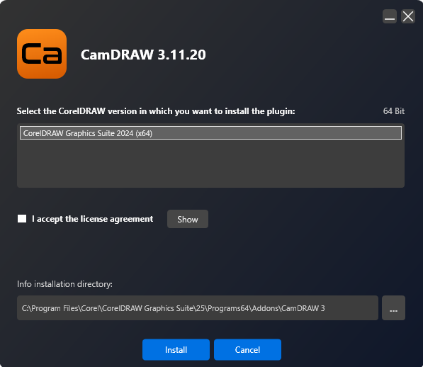
CamDRAW is a plug-in integrating into the Corel interface to allow it to generate G-Code. The first step is to download it here and to install it. Make sure you’re affecting it to the right version of CorelDRAW.
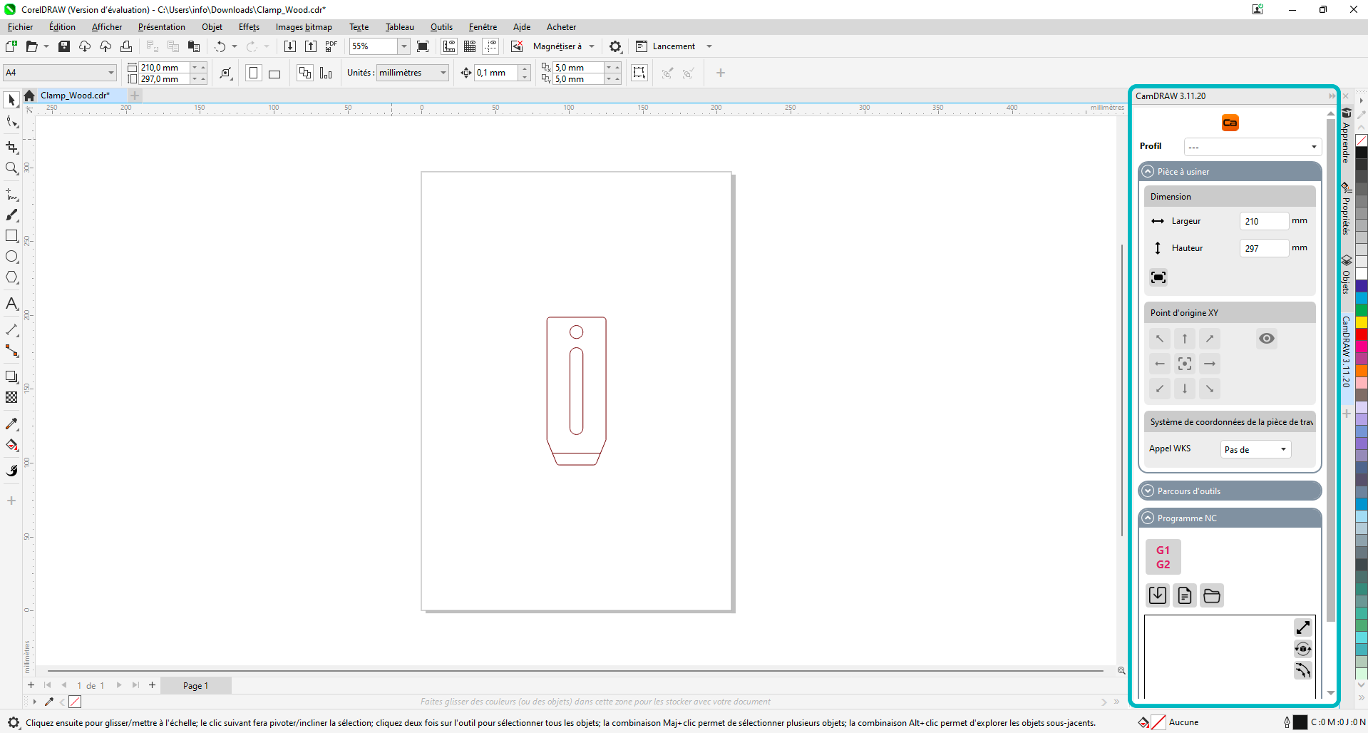
After restarting your computer, you should find the plugin directly available in your CorelDRAW interface under Tools > CamDraw. It will launch a side panel in your CorelDRAW interface.

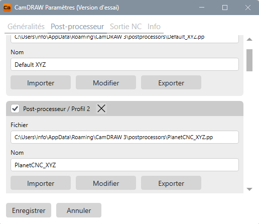
Before going any further, you’ll have to install the proper post-processor for your machine on CamDRAW. A list of the available presettings is available here for download. In our case, we need the PlanetCNC_XYZ post-processor.
Unzip the presettings folder and paste the files under C:\Users\Info\AppData\Roaming\CamDRAW 3\Postprocessors
To install a post-processor in CamDRAW, you then need to click on the Ca logo in the side panel, and add the one you need, then make sure it is selected in the side panel dropdown list.
2/ Create tools in our tool library
We usually suggest to start by encoding all the end mills you want to use for your job before starting to program operations. In the case of this simple clamp, we’re going to use a 6 mm downcut end mill.
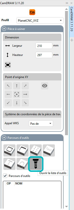
To access the Tool Library, go to the side panel under Toolpath > Open Tool List.
The menu is pretty straightforward: you can add a new tool, name it, and define its parameters. Note that you will already have to append feeds and speeds values to your tools, that will be reused by the operations, but you can always modify them on the operation level.
Unlike other CAM software, you’ll have to calculate your Feeds & Speeds by yourself, and there’s no available plugin to simplify this task. You can refer to our dedicated article to know more about how to do this.
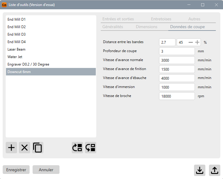
The different tool parameters you’ll need are the following:
- Dimensions: parameters of the end mill
- Cutting parameters: your feeds and speeds, as well as the depth of cut
- In and Out: if you want to program lead in/out or ramp
3/ Create toolpaths with CamDRAW
Now that everything is set up, we can import our vector drawing (if not done yet). The .*DXF file is available here: .
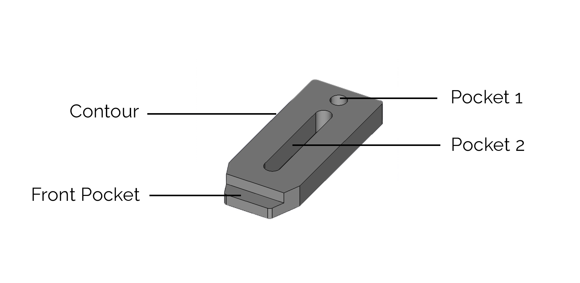
As a reference, the 3D view of the clamp we’re going to mill is as follows:
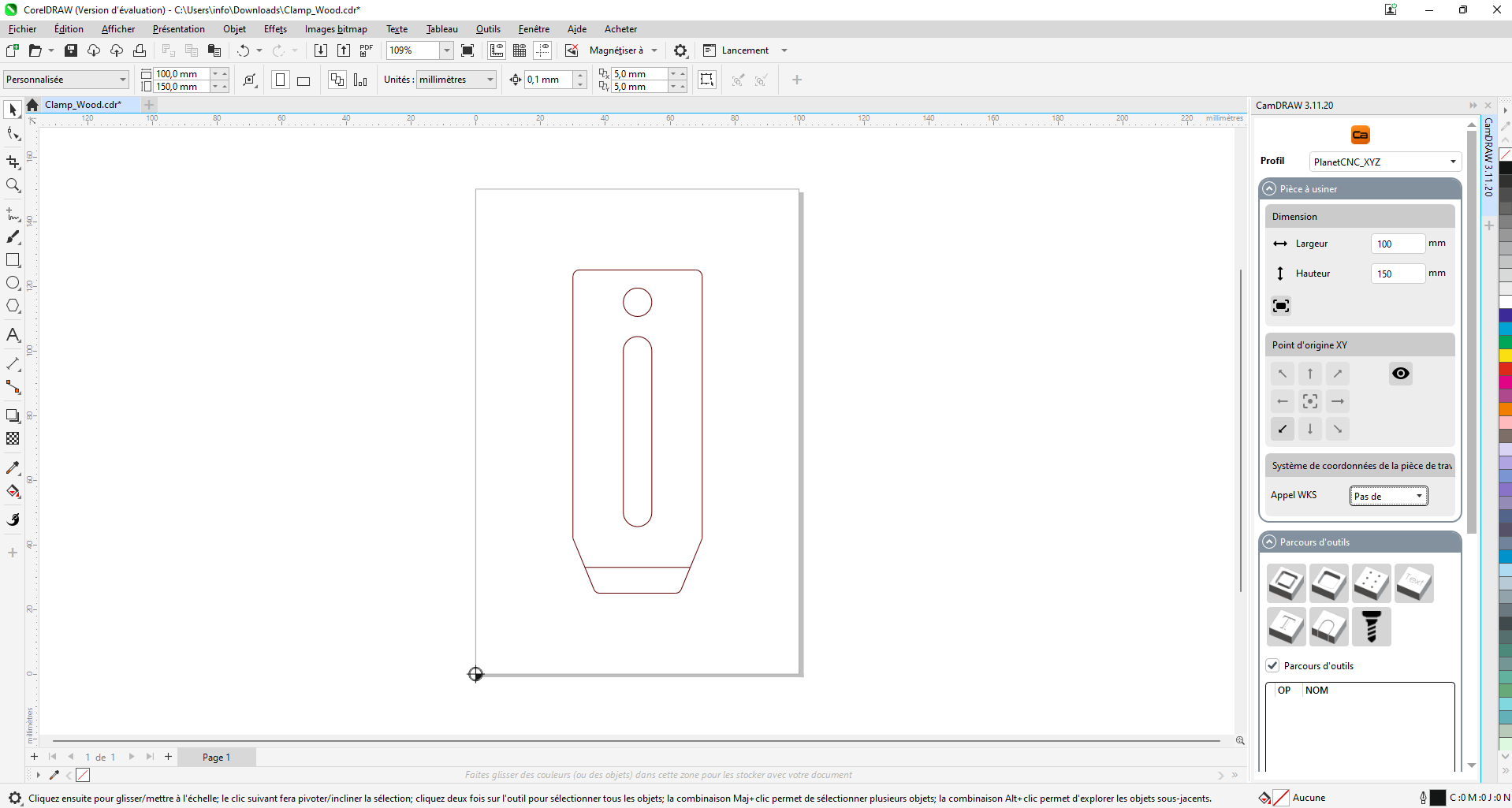
 Our part is 100x40mm. In the first section of the side panel, we’re going to define the coordinate convention:
- a working area of 150x100mm
- the origin in the bottom left corner
You can do as you wish, but always remember your choice to make sure the position of your operations are aligned with your stock. In CamDRAW, this is always done in 2D, under the XY axis. You’ll be able to define the origin of your Z-Axis further.
We can now start to define our different operations. Note that you cannot switch the order of the operations after you programmed them, so define your order from the beginning. For example, you’ll always want to mill your pockets before the contour of your clamp to make sure it is well attached when doing the pocket operations.
Our milling job consist of 4 elements:
- Two pockets inside the clamp
- A semi-pocket in front of the clamp
- A contour around the clamp
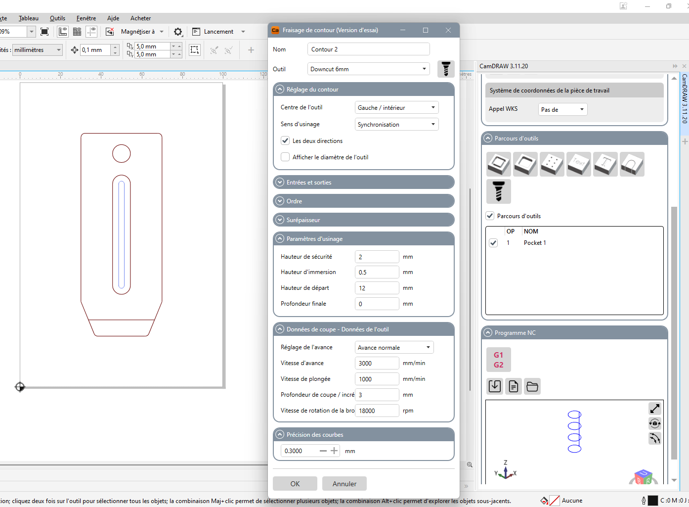
Let’s start by making the Pocket 1. For this, select the round on the drawing and click on Machining Type. Here, we’re going to use Pocket.
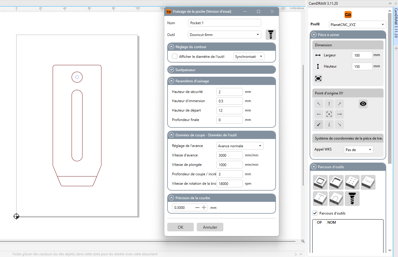
A new menu opens with different sections. You can leave most parameters standard for simple operations, but you have to check the following ones:
- Name your operation to clarify your job
- Define the tool you’re using – here our new 6mm downcut tool
- Machining parameters: this is where your Z-axis convention becomes important. If you want to measure the Z0 on top of your workpiece, you starting height will be 0 and your final depth will be a negative value. You can also use positive value only, with a starting height of the height of your stock – here 12mm - and a final depth of 0mm. This is the convention we’re always using in our tutorials.
- Cutting data: they are automatically imported from your Tool list, but you can change them if needed.
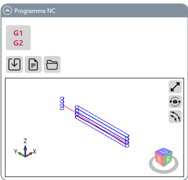
The second internal pocket will have to be done with a Contour operation. Select the outline of the long pocket, and select Contour in Machining Type. Here again, we’re going to select our end mill, and it is especially important to select Internal when choosing if the tool path is to be centred or outside the vector outline. The rest of the parameters are similar to our first pocket.
Tip : after making those first two operations, you can visualize your tool path by clicking on G1G2 to check if everything looks similar to what you want.
The third pocket in the front will also be done with the Contour operation, by selecting External this time. We’re also going to put the final depth of our operation to 6mm, to create a pocket instead of a milling operation going through.
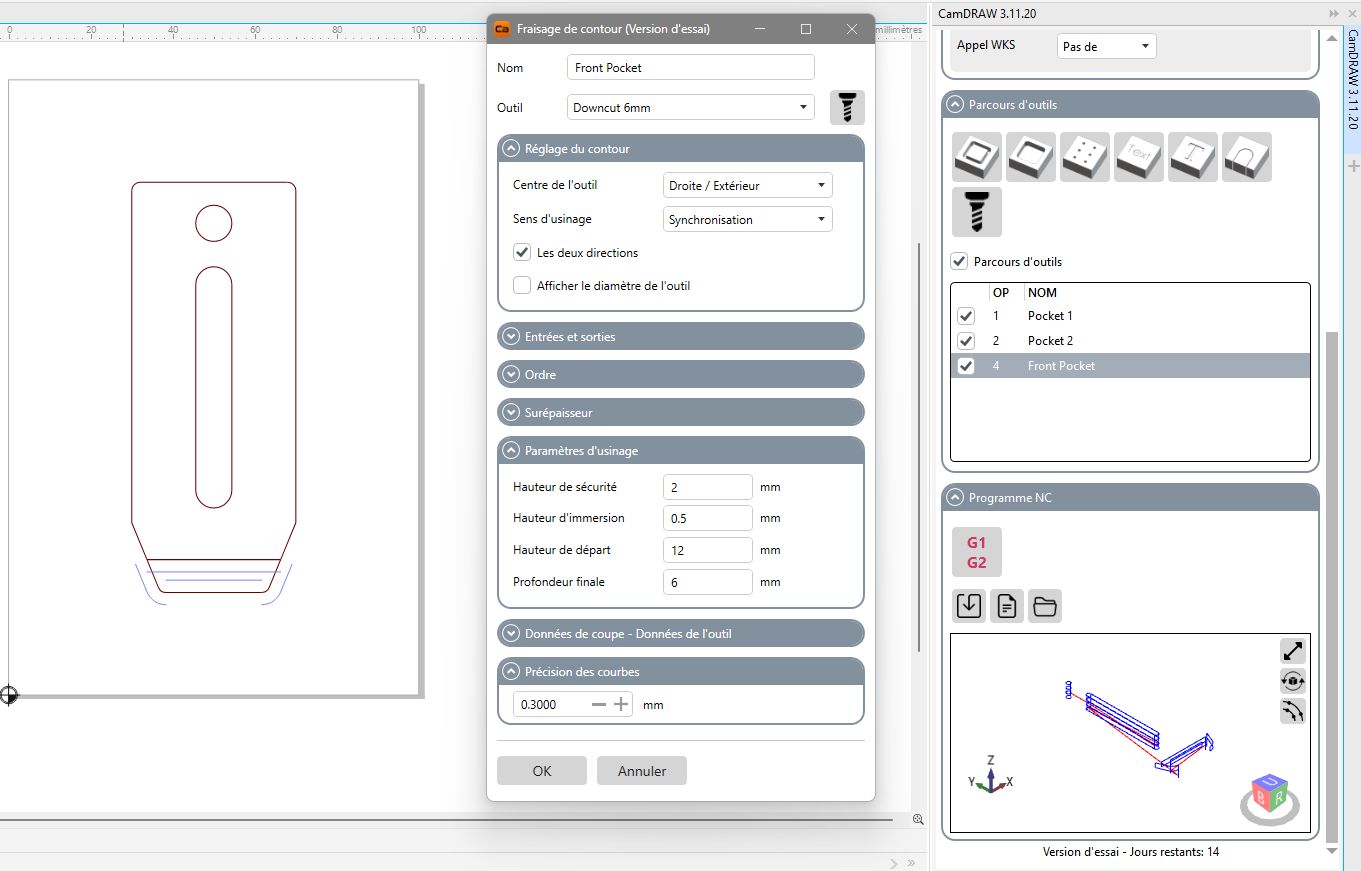
Last but not least, we’re going to make a Contour operation to outline the clamp in itself, with similar parameters as the previous operations.

Note that there are no tabs option in CamDRAW, forcing you to select a clamping system that is safe and will prevent your part from flying away in the room. Our experience is that CorelDRAW + CamDRAW is best suited for big parts attached through a proper vacuum system, and for engraving or sign making.
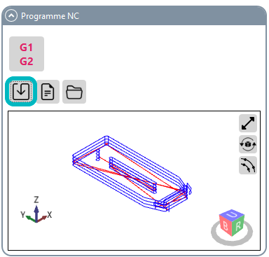
Once done, you can check the visual tool path to make sure everything looks good and export your G-Code by clicking on this button.
4/ Mill your part
You’re now ready to mill your clamp! We have a tutorial on how to use your Mekanika machine for the first time when you generate your G-Code, you can find it here.
5/ Additional note: tips on vector drawing for CNC milling
There are a few things to pay attention to when drawing for CNC milling:
- Imagine the operations from the beginning: are you going to engrave, make a pocket or a contour?
- Draw while already having the end mill in mind for the job, it will allow you to plan outlines and shapes accordingly.
- Pay attention to angles: in pocket and cutting operations, a cylindrical end mill cannot mill < 90° angles. You can refer to our article on dogbones to go around that issue.
- If you’re doing 2.5D and several operations, plan if your tool path is going to be centred, internal or external to your outline
After a few trial and error, you’ll have the experience to project yourself into the milling while drawing, making the process a breeze!