Now that your machine is installed and that you've tested it by cutting out the clamps or other files available on our site, it's time to create your own cutting file. There are several possibilities, and in this article, we're going to keep things as simple as possible, so that even if you're new to CNC milling, you'll be able to get started in no time!
We'll look at how to import a *.dxf file into PlanetCNC, for Mekanika CNC machines in particular.
Turn the shape you have in mind into a digital drawing
Do you have a very precise idea of what you want to cut? To start with, don't go for any embellishments, choose a simple shape with no relief. As an example, we're going to cut out a seahorse throughout this tutorial.
First, you'll need to vectorize the shape. The vectors will give the machine the coordinates it needs to find its way.
One solution for vectorization is to use 2D drawing software such as Illustrator, Inkscape or Corel Draw. If you're new to vector drawing, you can draw on paper, scan it and then import it into the drawing software to redraw the contours.
Whatever path you decide to follow, you can then save your file in *.dxf format. You can download the file we'll use for this article here :
Note: not yet comfortable with vectorization? You can buy ready-made *.dfx files on platforms like Etsy, for example.
Warning: the quality of your vector file will highly influence the quality of your cut. A clean layout will result in a clean machine path.
Move your drawing to Planet CNC
As you may have understood by now, PlanetCNC is the control software we have chosen to drive our machines. From a *dxf file, it can generate a Gcode that your machine can read to machine your cut-outs. We invite you to read these two previous articles to learn the basics of software control and the language specific to CNC milling.
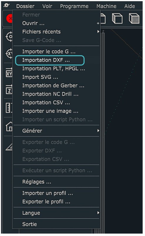
To import you *.dxf file, select Folder > Import DXF. This opens a window with various settings options. We'll show you how to go through them to quickly cut your first outline.
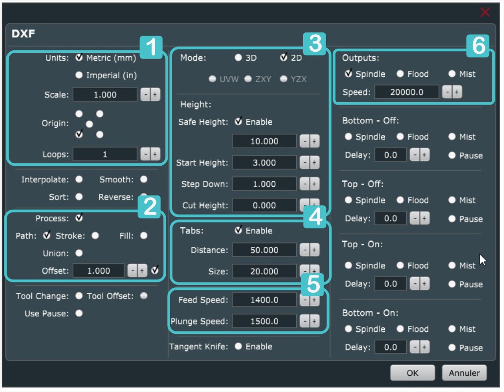
1 - The basics: units, scale and origin
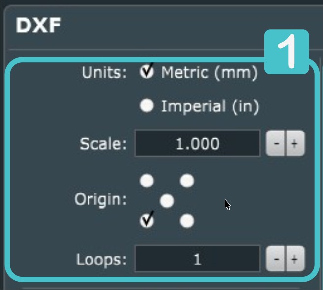
First, choose the "Units" in which you wish to work (in this case mm). If you worked in the same unit of measurement (mm) when creating your DXF, enter the number 1 in the field specifying the 'Scale'. If you used cm as the unit, enter 10 to obtain a shape with the correct measurements. Be sure to check the scale specified each time you import the DXF, especially if you are used to changing this data, as your parameters are saved from one import to the next.
To position the DXF in the machine workspace, we have 5 'Origin' choices. Tick the box at the bottom left the work with the standard approach we're explaining in all our tutorials.
The Gcode should only be read once, so enter the number 1 in the "Loops" field.
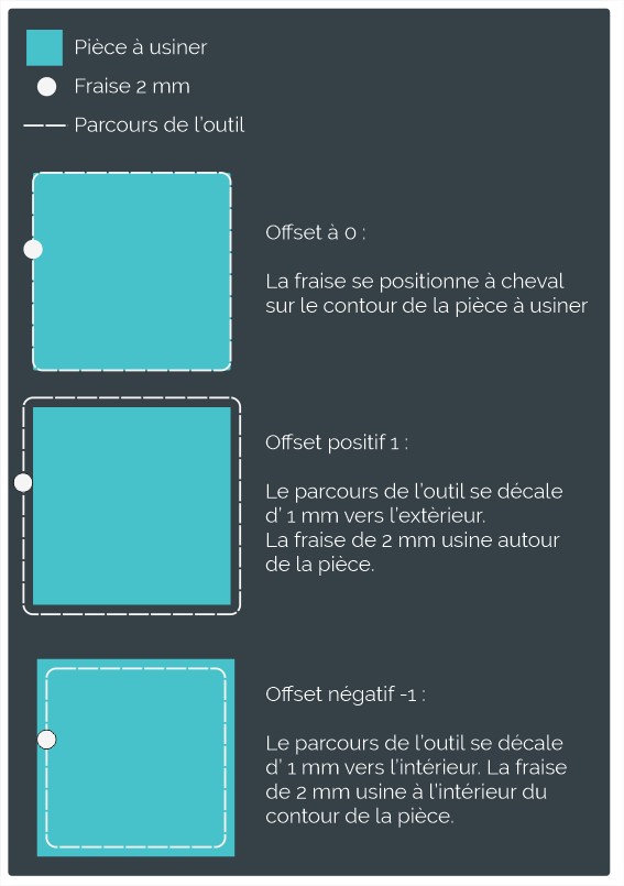
2 - "Process" defines the path your end mill will take
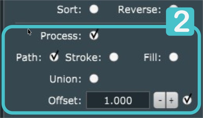
To generate the toolpath, click on "Path". This will centre the end mill on the path.
You can use the offset field to set the diameter of the tool you have chosen. The offset can be positive or negative. If you simply want to cut the seahorse, specify a positive offset. Always note an offset of half the diameter of your cutter, 1 for a 2 mm tool for example. This will give the shape exactly the measurements you want.
If you want to keep the hollowed-out part of the seahorse so that it is not distorted by the diameter of the cutter, enter a negative offset. -1 always for a 2 mm cutter. This will enlarge or reduce the line. As the end mill is placed right on the line, the offset allows the tool to remove the right amount of material at the right place so that the shape retains its initial appearance.
3 - The various heights
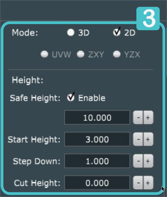
Once the cutting path and tool have been defined, let's move on to the z parameters. To do this, you'll need to fill in all the information in the 'Height' section. Before you do that, check 2D Mode, which gives you access to all the height parameters.
Tick the first field, 'Safe Height', which keeps the tool at a set height throughout its journey away from the cut. This feature is particularly useful for avoiding collisions in the chosen clamping device. Here we have entered a height of 10 mm.
"Start Height" corresponds to the height of your stock (bruto material you're milling), in this case 3 mm.
"Step Down" is used to define the depth of cut. Here we've chosen a cutting depth of 1 mm, bearing in mind the following formula: the cutting depth must always be less than half the diameter of our cutter.
Finally, 'Cut Height' (maximum cutting depth) indicates how deep to cut our raw material. If you want to cut your material completely, enter 0. If you want to groove your material, you can enter a maximum cutting depth that is less than the total height of the stock. Conversely, you can also choose to make a slight cut into your spoilerboard to ensure a clean cut. In this case, enter -0.3 for example.
PlanetCNC will calculate how many passes are needed to achieve the required depth of cut.
N.B. It is perfectly possible to "think" in the other direction, i.e. indicate 0 for the starting height, -1 for the cutting depth and -3 for the maximum cutting depth. The cut will be the same, only the Gcode will be different with negative values in Z. Pay attention in where you do you Z-probing when choosing a cutting direction. In the case of negative Z values, it should be on top of your stock.
4 - Maintaining your cut-out: tabs
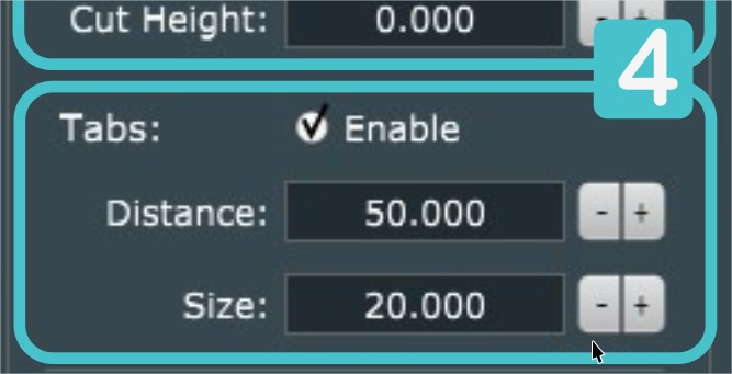
It is possible to set tabs to prevent your part from falling off and being projected in your workshop once it has been cut.
In the 'Tabs' area, you can define the distance between two tabs and their size, but unfortunately you can't choose their location. Here, we've chosen a distance of 50 mm and a size of 2 mm, and the tabs will then be positioned automatically.
5 - Feed and plunge speeds, spindle speed
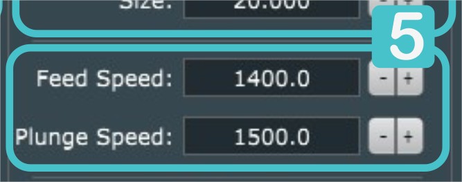
As final parameters in the cutting settings, we'd like to give you a few pointers on working speeds.
You'll find an article on our blog to find out more about cutting and feed speeds in CNC milling.
"Feed Speed' is the speed at which the machine moves in line when cutting. It is indicated in mm/min. You can choose a feed speed of 1400 mm/min based on the table in the above article for cutting MDF with a 2 mm cutter. With experience, you can fine-tune this setting.
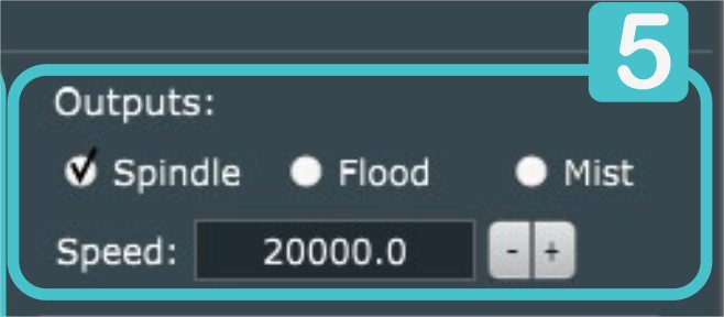
In the "Outputs" section, tick the "Spindle" box and enter 20,000 in the speed field. This will give your spindle a speed of 20,000 rpm.
6 - Spindle control
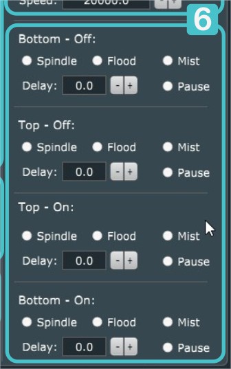
Last but not least, the last few lines of the DXF import window are reserved for controlling the spindle on/off, as well as a possible water flow for cutting materials other than wood. You have several options:
- switch off in the low position,
- switch off in the up position,
- switch on in the up position,
- switch on in the low position.
As far as the spindle is concerned, we advise you not to set any parameters here. If you leave all the boxes unchecked, the tool will be switched on and off automatically at the appropriate times.
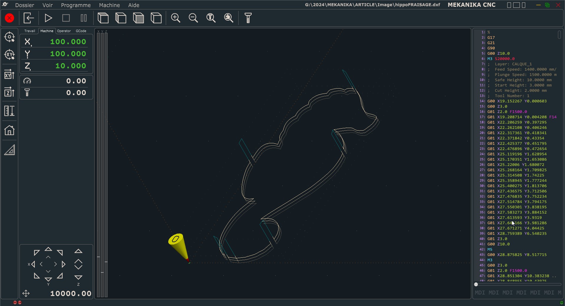
Now that everything is set up, click OK and your file is ready to be machined. The screen will show the tool path and the different cutting passes. Now all you have to do is clamp your piece, do the safety and positioning procedure and start machining!
Happy milling !
Pros and cons of DXF import in PlanetCNC
Here's a recap of the pros and cons of working directly with vector files on your CNC machines.
The advantages are:
- it's very quick to set up and it's a quick way to get a cut without experience
- there's no need for knowledge of CAD programs such as Fusion 360 or Vcarve, which take longer to learn
- it's practical for machining a single shape
- if you want to make different cut-outs from the same material, where the machining settings are the same, simply import and click OK. The settings remain the same from one import to the next.
The disadvantages are:
- for serial machining: the software performs the first pass on all shapes, rather than machining shapes one after the other, which requires longer machining times,
- it is not possible to machine in relief,
- it is only possible to machine to a single depth,
- the tabs are positioned automatically, sometimes in inappropriate places. You then have to juggle with the distances,
- you can't assign a machining order. For example, if you're machining a square shape with another in the centre, it's wiser to do the shape in the centre first and finish with the one on the outside.